
a humidifier

A technology for humidifiers and cabinets, applied in air humidification systems, heating methods, nebulizers for treatment, etc., can solve the problems of shortening the service life of humidifiers, wasting medicinal materials, not beautifying the environment, smelling or human health care, etc. To achieve the effect of improving the anti-backflow, improving the service life and good medicinal effect

Inactive Publication Date: 2016-09-21
黄俊杰
View PDF9 Cites 0 Cited by
  • Summary
  • Abstract
  • Description
  • Claims
  • Application Information

AI Technical Summary

Problems solved by technology

[0003] The function of ordinary humidifiers is to atomize pure water to increase air humidity. There is no structure designed to prevent medicine boxes. Using this type of humidifier does not have the effect of beautifying the environment or human health, and its function is relatively simple.
[0004] Medicinal effect humidifier is to set medicine box in the humidifier, place aromatherapy materials or other medicinal materials in the medicine box, and the atomized water vapor flows through the medicine box so that the air contains medicinal material molecules, but ordinary medicinal material humidifiers are not installed The diversion structure makes the water vapor fully contact with the medicine box. The water vapor can only contact the medicinal materials in the medicine box near the mist outlet. Not yet used up, waste of medicinal materials
In addition, there is no anti-backflow structure in the humidifier. The water vapor contains medicinal material molecules. After condensation and reflow on the inner wall of the mist outlet, it is easy to corrode the atomization components below the mist passage, which greatly shortens the service life of the humidifier.

Method used


Image

  • a humidifier
  • a humidifier
  • a humidifier

Examples


Embodiment Construction

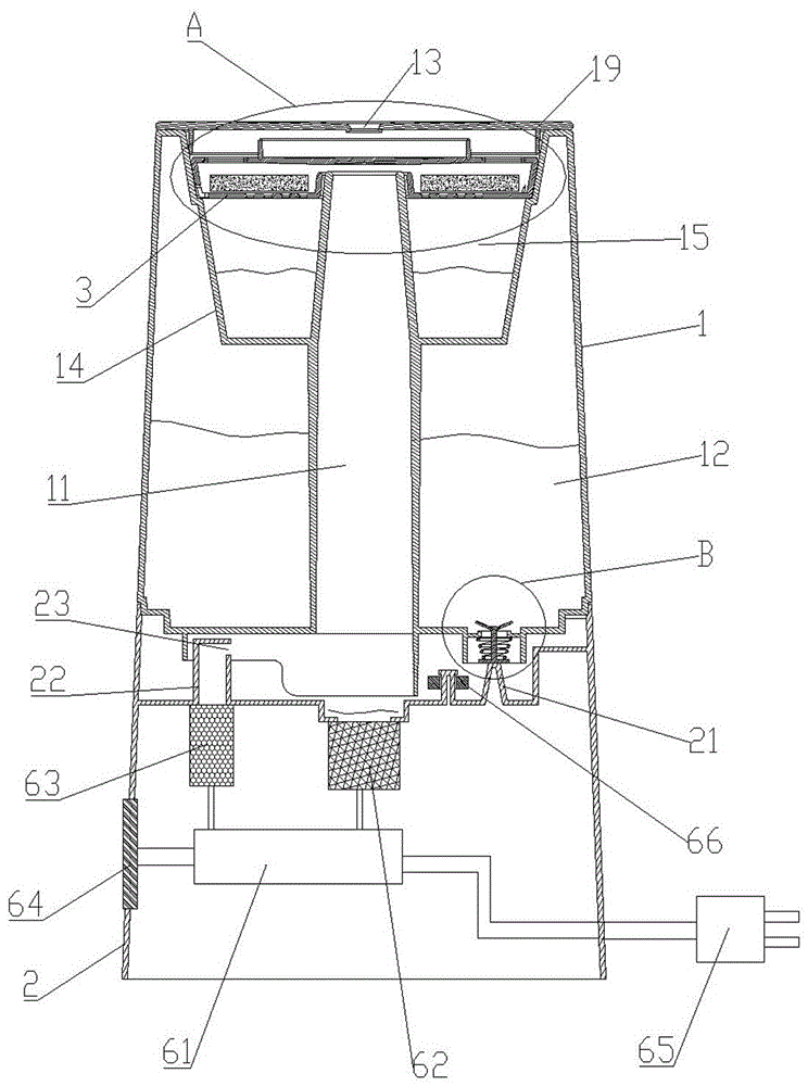
[0020] As shown in the figure, the humidifier proposed by the present invention includes: an upper box body 1 and a lower box body 2 fixedly connected, the lower box body 2 is provided with an atomization component, and the inner cavity of the upper box body 1 is divided into a mist outlet channel 11 and the water storage chamber 12, the top surface of the upper box body 1 is provided with a mist outlet 13, and both ends of the mist outlet 11 communicate with the atomization assembly and the mist outlet 13 respectively.

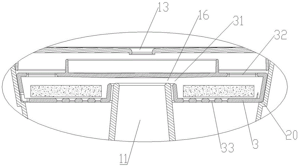
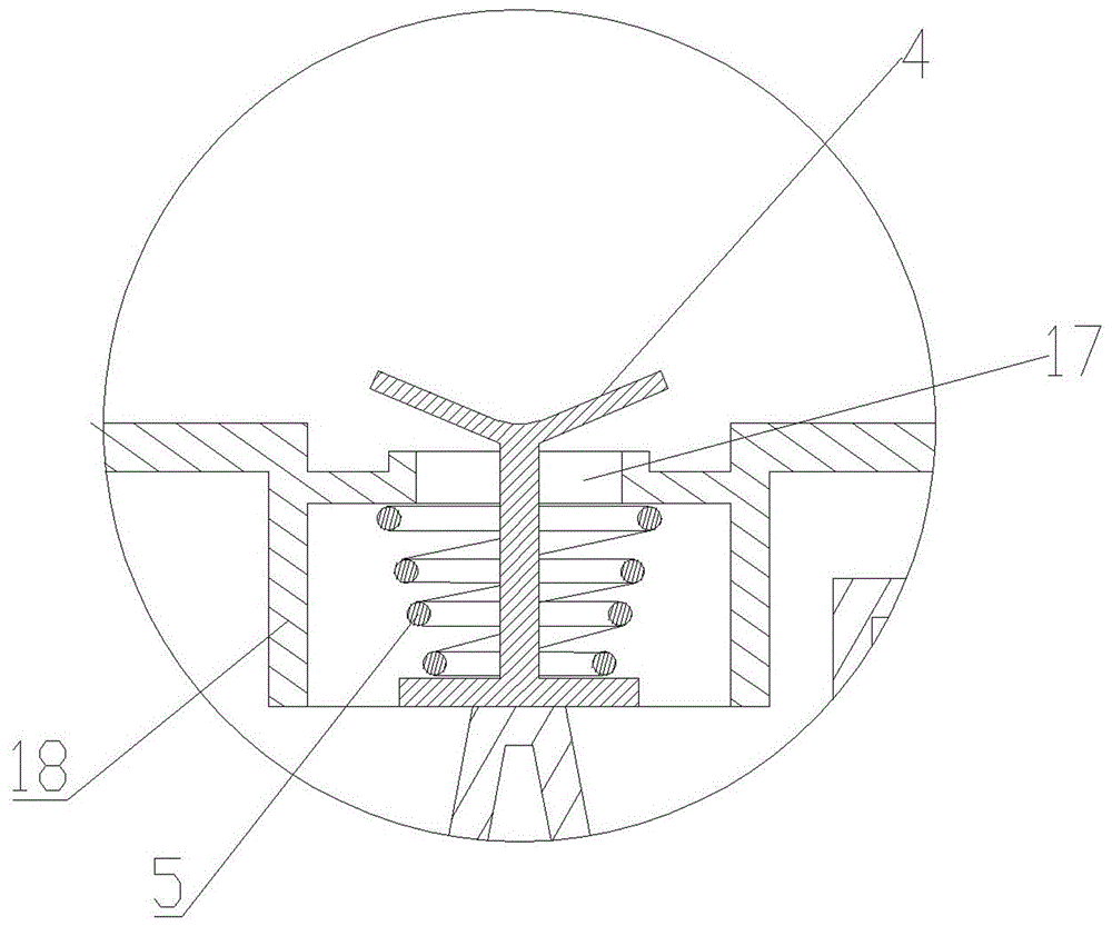
[0021] A partition 14 is sealed between the outer wall of the upper end of the mist outlet 11 and the inner wall of the top of the upper box 1. The partition 14 is recessed inward to form a sewage chamber 15. The top of the sewage chamber 15 is provided with a medicine box 3 for containing medicinal materials. 3. The inner side of the top surface extends to cover the opening at the top of the mist outlet channel 11. The top side wall of the mist outlet channel...


PUM


Abstract

The invention discloses a humidifier, comprising: an upper box body and a lower box body, an atomizing component is arranged in the lower box body, the inner cavity of the upper box body is divided into a mist outlet channel and a water storage room, and the top surface of the upper box body is provided with an atomizing component. There is a mist outlet, and the two ends of the mist outlet are respectively connected with the atomization component and the mist outlet. The top of the sewage chamber is provided with a medicine box. The inner side of the top surface of the medicine box extends to cover the top opening of the mist outlet. The top side wall of the mist outlet is provided with an air outlet adjacent to the medicine box. The air inlet and the outer side of the top surface of the medicine box are evenly provided with air vents that communicate with the mist outlet, and the bottom surface of the medicine box is evenly provided with liquid leakage holes. In the invention, a diversion structure is arranged between the mist outlet and the medicine box, so that the water vapor can fully contact the whole medicine box, and the materials in the medicine box can be fully utilized. component.

Description

technical field [0001] The present invention relates to a humidifier. Background technique [0002] A humidifier is a household appliance that increases humidity in a room. Humidifiers can humidify specific rooms, or they can be connected to a boiler or central air conditioning system to humidify an entire building. Existing humidifiers can be divided into two categories according to their efficacy: one is an ordinary humidifier, and the other is a medicinal humidifier. [0003] The function of ordinary humidifiers is to atomize pure water to increase air humidity. There is no structure designed to prevent medicine boxes. Using this type of humidifier does not have the function of beautifying the environment or human health, and its function is relatively simple. [0004] Medicinal effect humidifier is to set medicine box in the humidifier, place aromatherapy materials or other medicinal materials in the medicine box, and the atomized water vapor flows through the medicine...

Claims


Application Information

Patent Timeline
Patent Type & Authority Patents(China)
IPC IPC(8): F24F6/12A61M11/00
Inventor 黄俊杰
Owner 黄俊杰
Learn More