Terminal position identification method and system thereof

A method for determining the location of a terminal and a technology for determining the location of the terminal, which are used in radio wave measurement systems, positioning, measuring devices, etc.

Inactive Publication Date: 2006-11-15
NEC CORP
View PDF0 Cites 5 Cited by
  • Summary
  • Abstract
  • Description
  • Claims
  • Application Information

AI Technical Summary

Problems solved by technology

[0017] However, in the above-mentioned existing positioning method, signals from three or more base stations or three or more GPS satellites are required, but in an environment where the total number of base stations or GPS satellites that can be measured is only two, due to two There are two intersection points of the subcurve, so the problem is that the position of the terminal cannot be approached, and the position of the terminal cannot be determined with high precision

Method used


Image

  • Terminal position identification method and system thereof
  • Terminal position identification method and system thereof
  • Terminal position identification method and system thereof

Examples


Embodiment 1

[0175] Embodiment 1 of the present invention will be described with reference to the drawings.

[0176] Image 6 It is a diagram showing the outline of a mobile communication network.

[0177] The mobile communication network is composed of a terminal 21, a base station 22, a base station 23, a fixed network 24, and an RNC 25. When communicating, the terminal 21 establishes a connection with the RNC 25 via a wireless link established with the base station 22 or the base station 23 .

[0178] The base station 22 and the base station 23 are connected to the fixed network 24 and controlled by the RNC 25 . In addition, base stations 22, 23 form a plurality of communication areas (hereinafter referred to as sectors), for example, base station 22 forms sectors 26, 27, 28, base station 23 forms sectors 29, 210, 211, and each sector passes through Scrambling code (scrambling code) to distinguish. Furthermore, the base stations 22 and 23 continuously transmit a signal obtained by s...

Embodiment 2

[0264] Embodiment 2 of the present invention will be described with reference to the drawings.

[0265] In the first embodiment described above, the case where the RNC 25 performs arithmetic processing to specify the position of the terminal 21 has been described, but it is conceivable that the terminal 21 performs arithmetic processing for determining the position. Therefore, in Embodiment 5, an example in which the terminal 21 performs arithmetic processing for determining a position will be described.

[0266] Figure 20 It is a configuration diagram showing a terminal 21 having a function of performing arithmetic processing. In addition, only the components necessary for the description of the present embodiment are shown in the drawings.

[0267] The wireless signal receiving unit 2401 has a function of receiving a signal transmitted from a base station, and the wireless signal transmitting unit has a function of transmitting a wireless signal to the base station.

[0...

Embodiment 3

[0351] Embodiment 3 of the present invention will be described with reference to the drawings.

[0352] In the above-mentioned Embodiment 1 and Embodiment 2, the method of calculating the candidate points 13 and 14 by the RNC 25 or the terminal 21 by obtaining the intersection point of the hyperbola 11 and the circle 12 has been described, but it is also conceivable to obtain 22 as the center (circle 12) and the circle with the base station 23 as the center to obtain two candidate points.

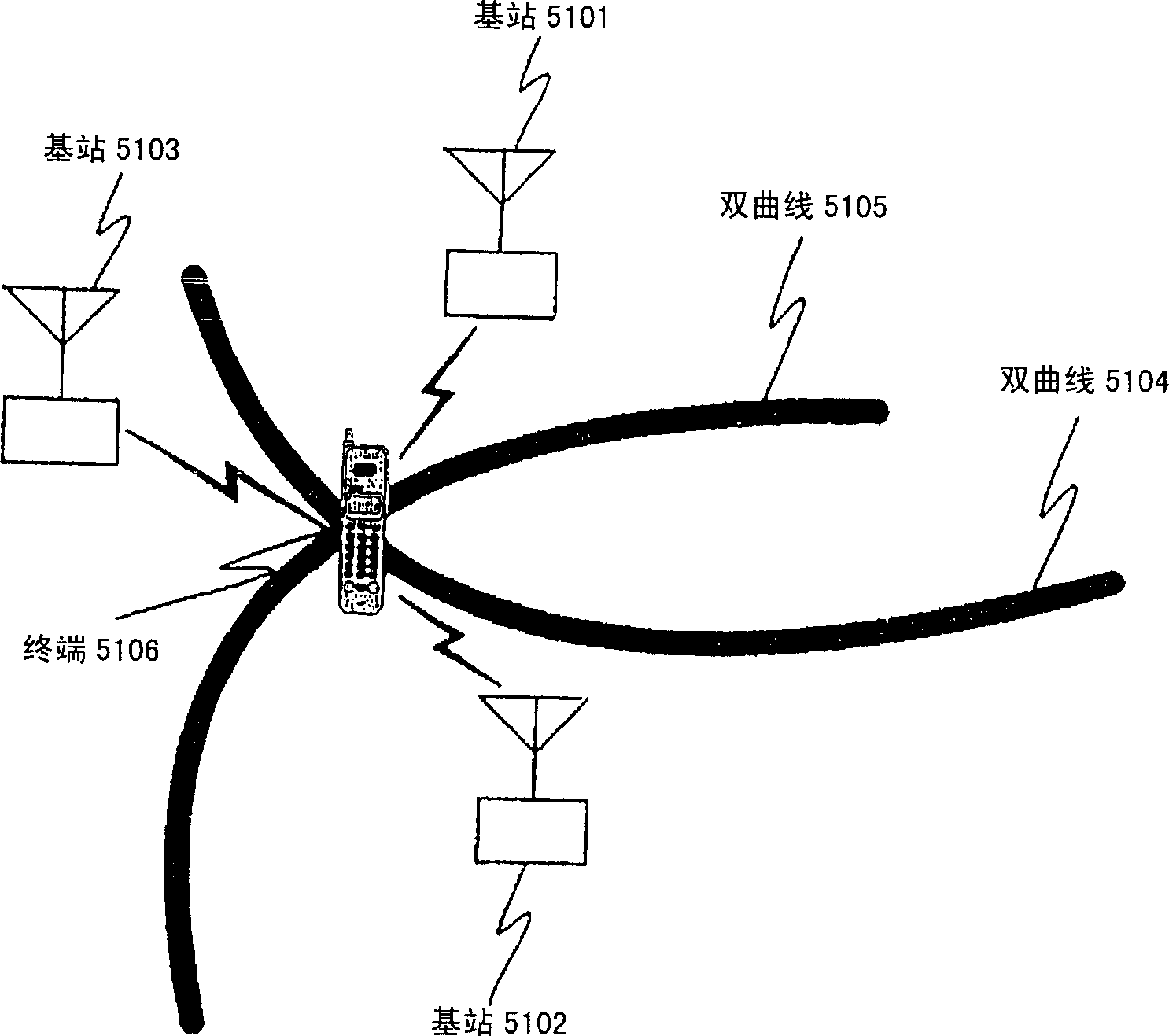
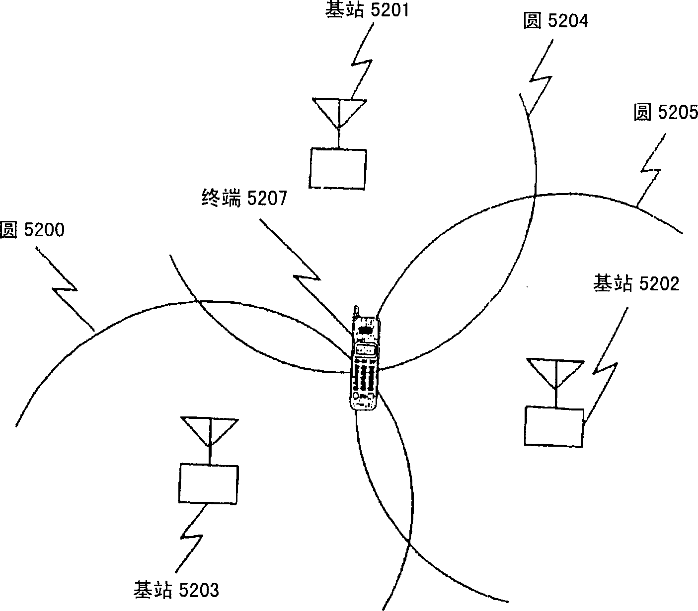
[0353] Figure 25 It is a figure showing the principle of determining the position of the terminal 21 in this embodiment.

[0354] In this embodiment, the circle 12 centered on base station 22 calculated according to the round-trip transmission time between terminal 21-base station 22 and the circle 11 centered on base station 23 according to the round-trip transmission time between terminal 21-base station 23 to calculate the two candidate points 13, 14 of the terminal 21.

[0355] Fi...


PUM


Abstract

The invention is to provide a technique for specifying the location of a terminal with a high degree of accuracy even in an environment in which the grand total of the number of base stations and GPS satellites that can be measured is only two stations. A hyperbola 11 is found from the difference between the reception time of a signal from a base station 22 and the reception time of a signal from a base station 23 in a terminal 21, and a circle 12 is found from the round-trip propagation time between the base station 22 and the terminal 21. Intersection points between the hyperbola 11 and the circle 12 is calculated to find a candidate point 13 and a candidate point 14. The terminal 21 is located in a sector 27, so that the candidate point 13 existing in the range of the sector 27 is specified as the location of the terminal 27.

Description

technical field [0001] The present invention relates to the field of mobile radio communications, and relates to a method for determining the geographic location of a mobile station in a mobile communications network. Background technique [0002] In order to more fully describe the current state of the art to which the present invention pertains, all of the patents, patent applications, patent publications, scientific papers, and the like cited or specified in this application are hereby incorporated by reference. [0003] In recent years, many methods have been reported as methods for specifying the position of a mobile phone terminal, and several positioning methods for specifying the position of a mobile phone terminal have already been standardized by a plurality of standardization bodies. [0004] As an example of the positioning method, there is a GPS positioning method using signals from GPS satellites. [0005] This method is standardized by the 3rd General Partner...

Claims


Application Information

Patent Timeline
Patent Type & Authority Applications(China)
IPC IPC(8): G01S5/14G01S19/12G01S19/46G01S19/48H04W64/00
CPCG01S5/14
Inventor 松田淳一
Owner NEC CORP
Why Eureka
Try Eureka