Mobile terminal, base station, and mobile terminal positioning method

A portable terminal and base station technology, applied in the field of portable terminals, can solve problems such as estimated distance deviation

Inactive Publication Date: 2010-08-18
KYOCERA CORP
View PDF3 Cites 0 Cited by
  • Summary
  • Abstract
  • Description
  • Claims
  • Application Information

AI Technical Summary

Problems solved by technology

[0007] However, in the prior art described above, the position of the PHS terminal is detected by calculating the estimated distance from each base station based on the radio wave strength of the signal. When the estimated distance is calculated based only on the radio wave strength in the same way in each place, there is a problem that the calculated estimated distance may be biased.
[0008] In addition, in the prior art described above, only the estimated distance to each base station is calculated using radio wave strength as a parameter, and the position of the PHS terminal is detected based on a plurality of circles having the estimated distance as a radius and each base station as a center. In this method, there is a problem that the accuracy of position detection can only be improved by adding base stations for PHS terminals to communicate with

Method used


Image

  • Mobile terminal, base station, and mobile terminal positioning method
  • Mobile terminal, base station, and mobile terminal positioning method
  • Mobile terminal, base station, and mobile terminal positioning method

Examples


no. 1 Embodiment approach

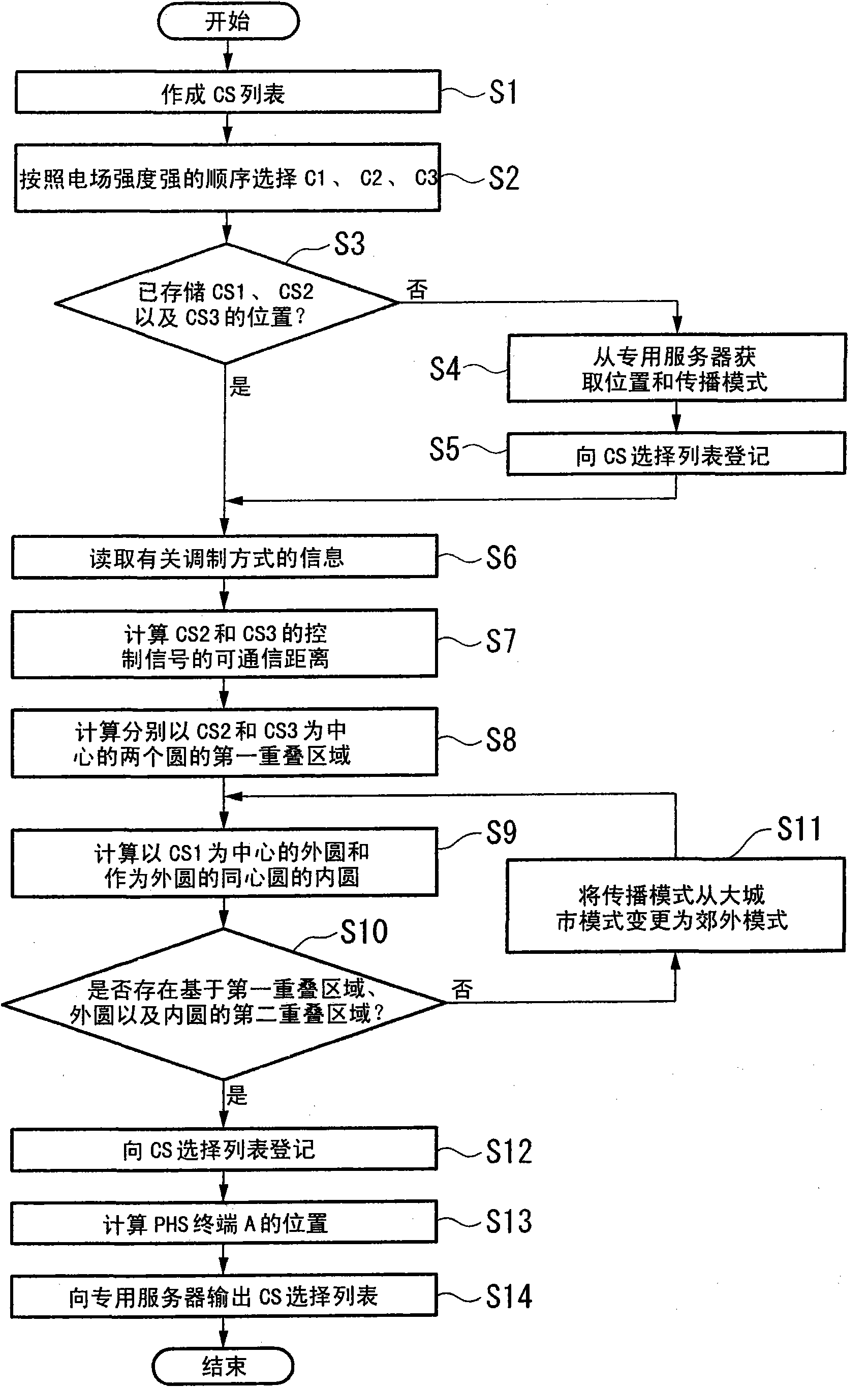
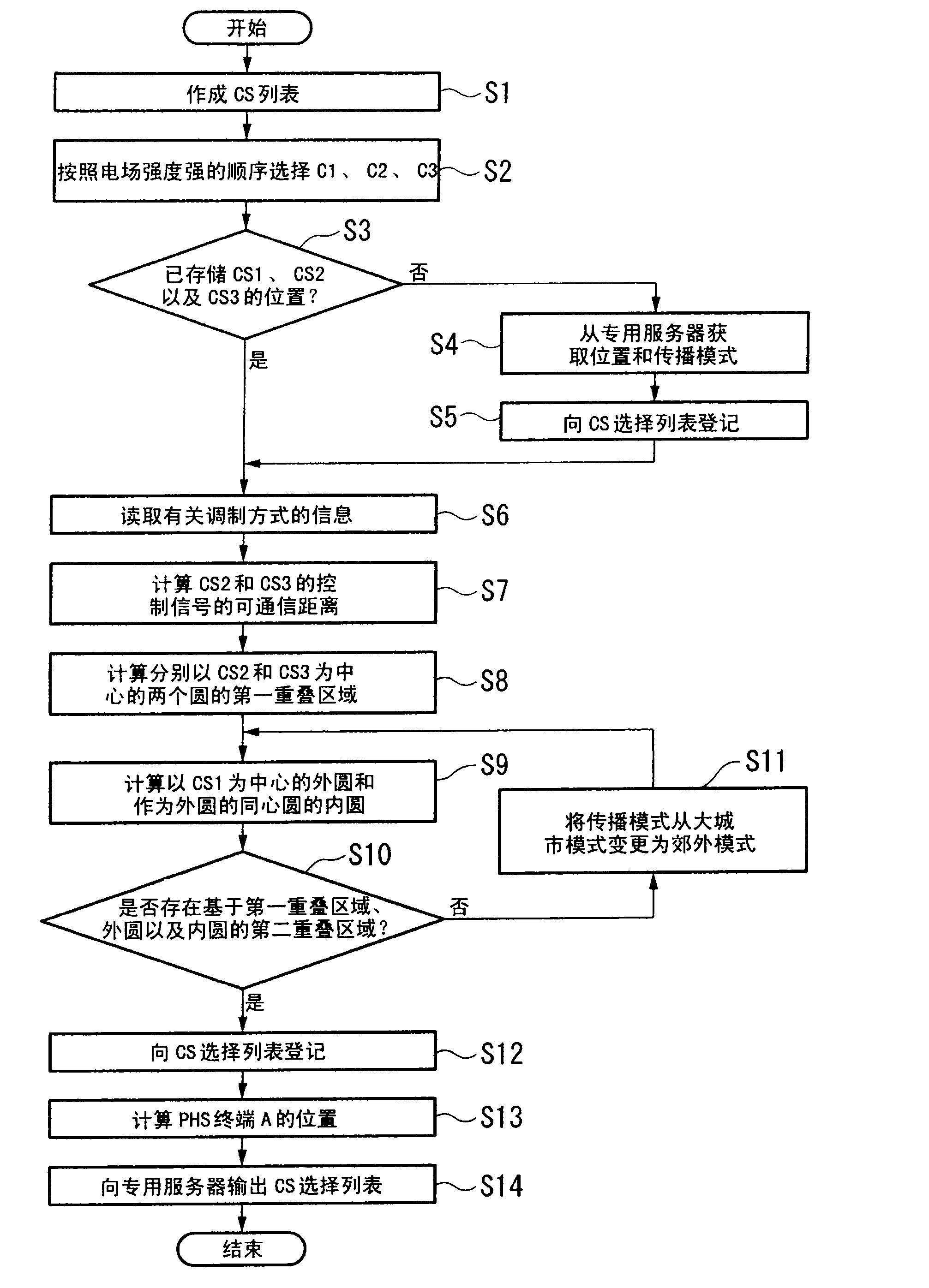
[0048] First, the first embodiment will be described.

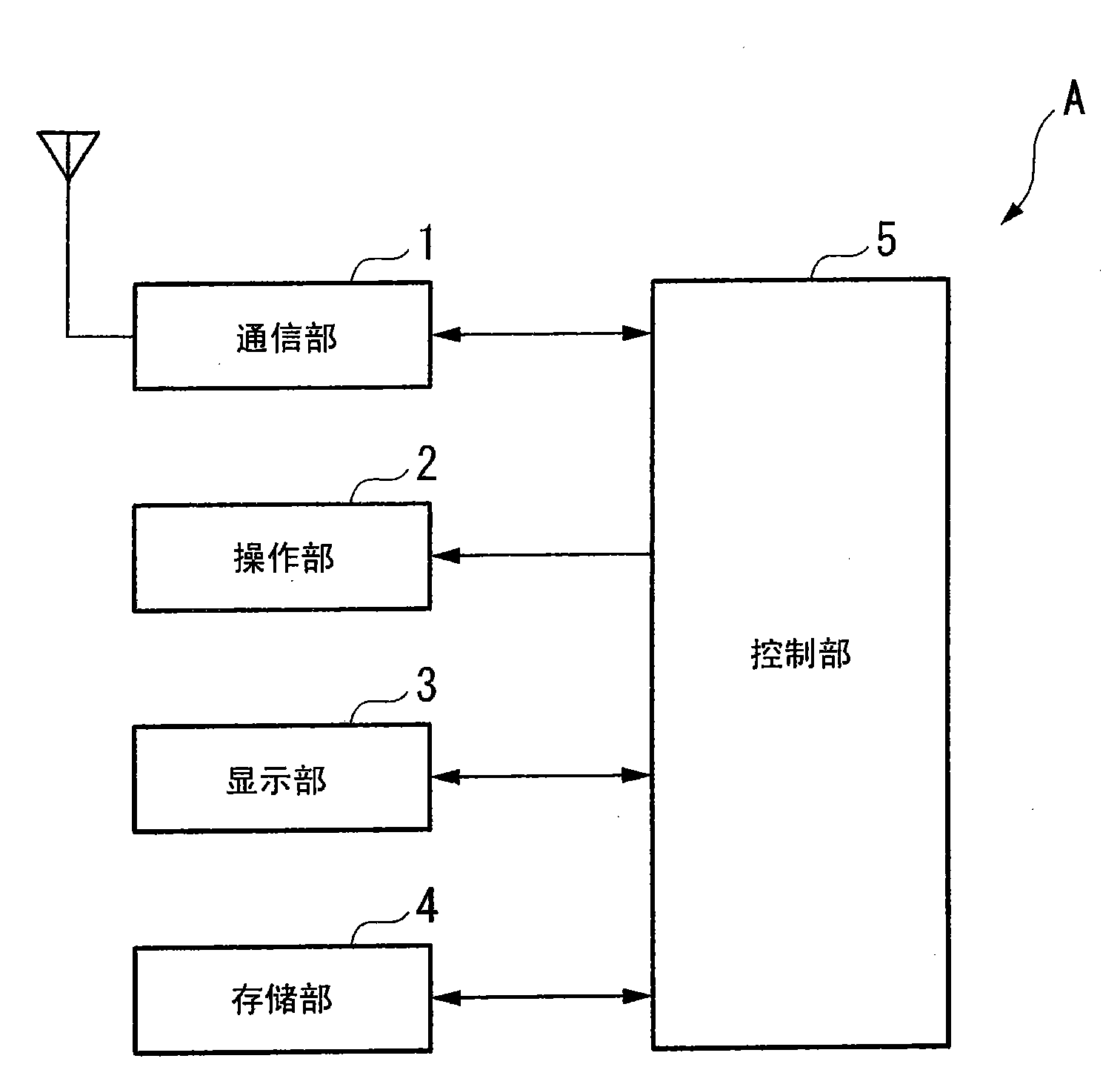
[0049] FIG. 1 is a functional block diagram of a PHS terminal A according to the present embodiment. As shown in FIG. 1 , the PHS terminal A is composed of a communication unit 1 , an operation unit 2 , a display unit 3 , a storage unit 4 , and a control unit 5 .

[0050] The communication unit 1 transmits and receives various signals with the PHS base station via a communication channel and a control channel based on the control of the control unit 5 . Furthermore, the communication network constituted by the PHS terminal A and the base station corresponds to an adaptive modulation method in which the modulation method of a signal (communication signal) transmitted and received via a communication channel is changed according to the communication state, and the communication unit 1 corresponds to the adaptive modulation method. Way.

[0051] The operation unit 2 is composed of various operation keys such as a power key...

no. 2 Embodiment approach

[0112] Next, a second embodiment will be described.

[0113] FIG. 8 is a functional block diagram of the PHS terminal A1 according to the second embodiment. As shown in FIG. 8 , the PHS terminal A1 is composed of a reception unit 21 , a transmission unit 22 , an operation unit 23 , a display unit 24 , a storage unit 25 , and a control unit 26 .

[0114] The receiving unit 21 is composed of an antenna 21a, a filter switching unit 21b, a first filter 21c, a second filter 21d, a mixer 21e, a local oscillator 21f, and a reception processing unit 21g, and based on an instruction from the control unit 26, the Receive various signals.

[0115] The antenna 21a receives signals from the base station. And, the output destination of the received signal is switched to the first filter 21c or the second filter 21d by the filter switching unit 21b based on an instruction from the control unit 26 .

[0116] The first filter 21c is a SAW (Surface Acoustic Wave) filter that attenuates unnec...

no. 3 Embodiment approach

[0147] Next, a third embodiment will be described.

[0148] Fig. 12 is a functional block diagram of the PHS terminal B1 according to the third embodiment. The PHS terminal B1 differs from the PHS terminal A1 of the second embodiment in that the receiver 21 and the transmitter 22 for transmitting and receiving signals are replaced by an adaptive array antenna communication unit 11 having an adaptive array antenna. However, in the PHS terminal B1, parts having the same functional components as those in the PHS terminal A1 according to the second embodiment are denoted by the same reference numerals, and description thereof will be omitted.

[0149] The PHS terminal B1 includes an operation unit 23 , a display unit 24 , a storage unit 25 , a control unit 26 , and an adaptive array antenna communication unit 11 .

[0150] The adaptive array antenna communication unit 11 as a modified component is composed of an antenna 11a, a mixer 11b, a first local oscillator 11c, a second loc...


PUM


Abstract

A mobile terminal includes: a communication unit which transmits / receives a signal modulated by a predetermined modulation method to / from three or more base stations; a storage unit which stores a plurality of propagation models indicating a signal propagation environment for each of combinations of the base stations in advance and stores position information on the base stations in advance; and a control unit which controls the communication unit and the storage unit. The control unit identifies a propagation model corresponding to the combination of the base stations among the propagation models stored in the storage unit according to the signal and calculates a signal communication-enabled distance in accordance with the propagations model. The control unit calculates a circle having a radius of the communication-enabled distance and a center at the position of each of base stations and acquires an overlap area where the respective circles are overlapped so as to specify the center position of the overlap area as the position of the mobile terminal.

Description

technical field [0001] The present invention relates to a portable terminal such as a portable telephone or a PHS (Personal Handy-phone System) terminal, a base station, and a method for determining the position of the portable terminal. [0002] This application claims priority based on Japanese Patent Application No. 2007-249737 filed on September 26, 2007 and Japanese Patent Application No. 2007-281688 filed on October 30, 2007 in Japan, and the contents thereof are incorporated herein. Background technique [0003] Patent Document 1 below discloses a position search method for a mobile device based on PHS that can accurately search for the position of a mobile device such as a truck or a loading / unloading pallet by accurately estimating the allowable error or the unloading time. [0004] In this position search method, a PHS terminal is installed on a mobile device, and the PHS terminal calculates the estimated distance to each base station based on the signal strength o...

Claims


Application Information

Patent Timeline
IPC IPC(8): H04W64/00G01S5/14G01S5/02
CPCG01S5/10G01S13/876G01S5/0252G01S5/02521
Inventor 三浦孝则
Owner KYOCERA CORP
Why Eureka
Try Eureka