Vehicle floor structure

A floor and vehicle technology, applied in the direction of superstructure, vehicle parts, superstructure sub-assembly, etc., can solve the problems of increasing material and labor costs, reducing mechanical strength, complicating the manufacturing process, etc.

Inactive Publication Date: 2006-11-22
HONDA MOTOR CO LTD
View PDF1 Cites 6 Cited by
  • Summary
  • Abstract
  • Description
  • Claims
  • Application Information

AI Technical Summary

Problems solved by technology

[0005] However, splitting the beam into two parts greatly reduced the mechanical strength, and additional members needed to be thicker than desired to compen...

Method used


Image

  • Vehicle floor structure
  • Vehicle floor structure
  • Vehicle floor structure

Examples


Embodiment Construction

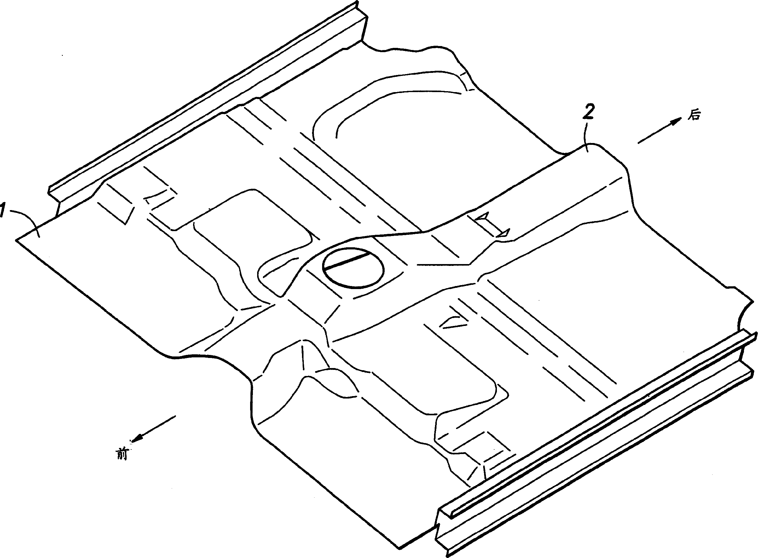
[0021] figure 1 is a partial perspective view of a vehicle floor panel 1 embodying the invention. As shown in the figure, the floor panel 1 is stamped and formed from a thinner steel plate, and has several raised beadings (not shown in the figure), which are used to accommodate various components connected to the floor panel 1 and increase the floor surface. Bending stiffness of panel 1.

[0022] Such as figure 1 As shown, the transverse center portion of the floor panel is formed by a floor tunnel 2 extending in the front-to-rear direction and having a trapezoidal cross-section to ensure the bending rigidity of the vehicle body around the transverse line.

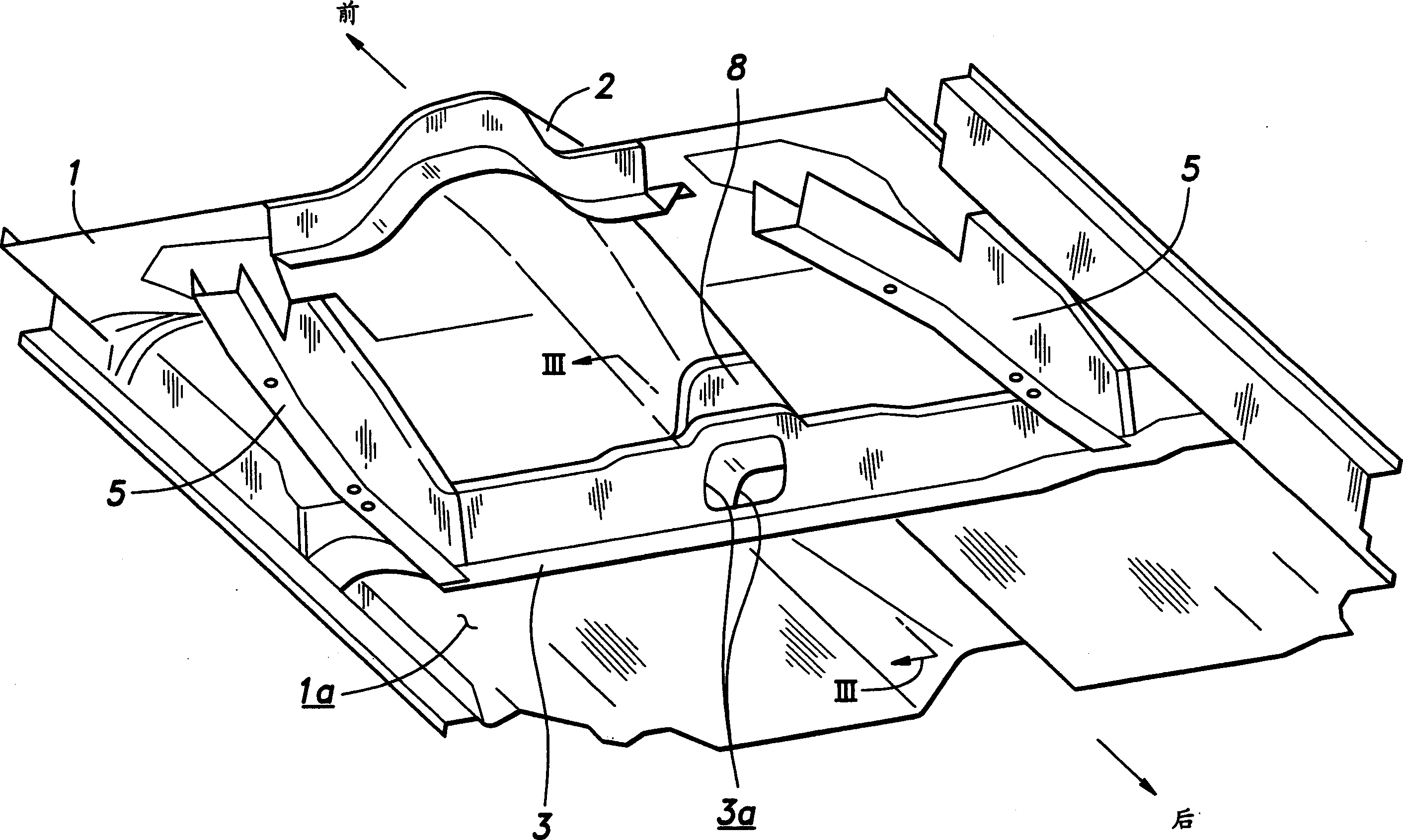
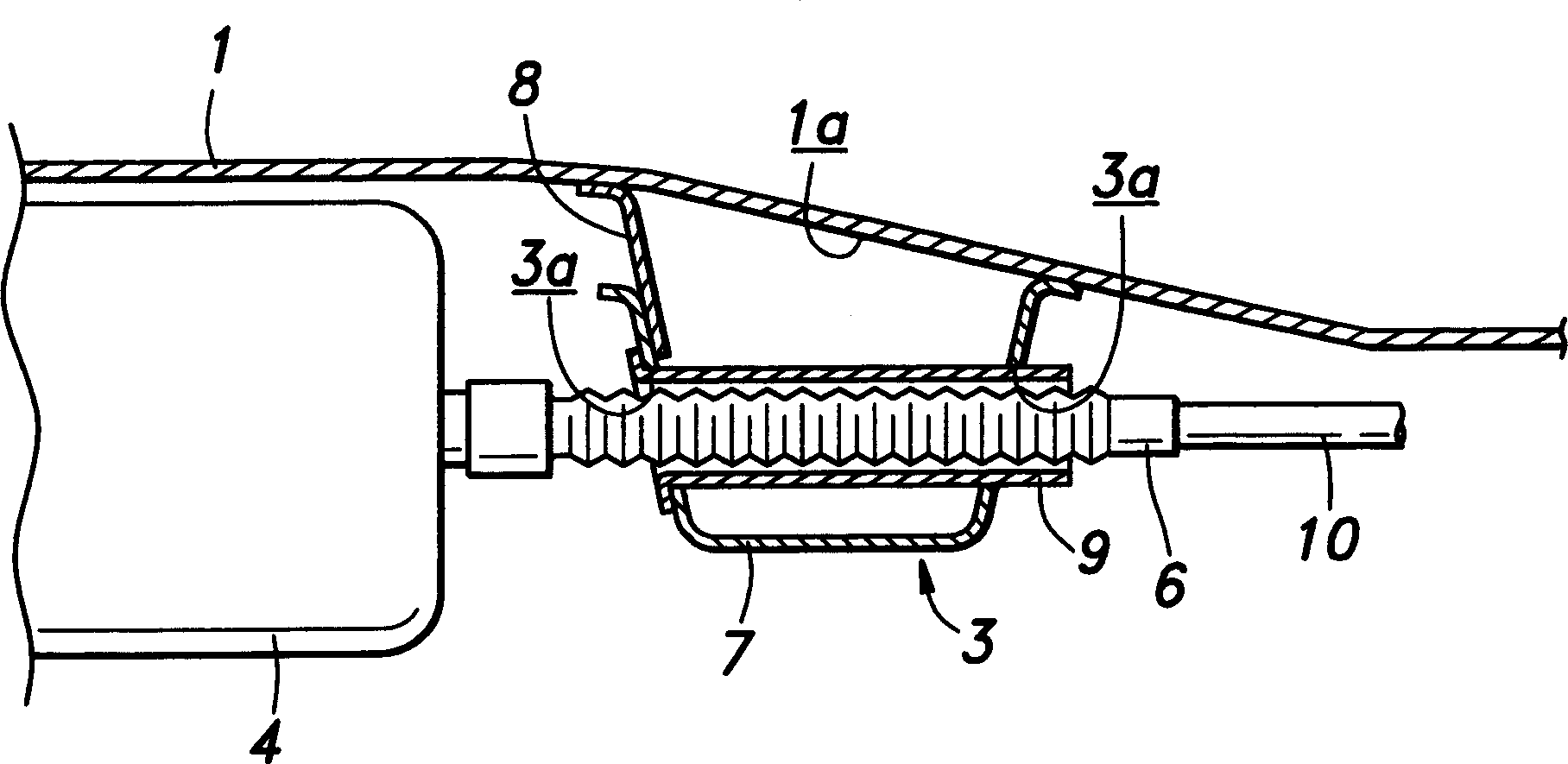
[0023] It is also required that the floor panel 1 ensures sufficient bending stiffness of the body around the longitudinal line. To meet this requirement, the lower surface 1a of the floor panel 1 is connected to a cross member 3 which extends transversely through the vehicle body and forms a figure 2 The illustrated ...


PUM


Abstract

To ensure the mechanical strength of a cross member (3) that extends laterally across a vehicle body and attached to a lower surface (1a) of a floor panel (1) without increasing the number of component parts, the cross member (3) is provided with a front and rear wall each defining an opening (3a). A tubular guide member (9) is fitted between the two openings. The cross member (3) is provided with an end plate (8) that fills the interior of a part of a floor tunnel that intersects with the cross member (3). A pipe (6) extending from a fuel tank (4) mounted on a lower surface (1a) of the floor panel (1) is passed through the cross member (3) via the guide member (9). Because the component part is passed through the cross member without splitting the cross member into two parts, the mechanical strength of the cross member is prevented from being reduced, and an overall mechanical strength can be ensured.

Description

technical field [0001] The present invention relates to vehicle floor structures. Background technique [0002] In some vehicles currently on the market, large components such as the fuel tank and engine are grouped under the floor panel. In this case, the remainder of the floor panel can be kept at a lower height by protruding the corresponding part of the panel upwards or towards the passenger compartment. In addition, by placing such a raised portion under the front seat, the inconvenience caused by the unwanted protrusion into the passenger compartment can be minimized (for example, see Japanese Laid-Open Patent No. 2002- 302071). [0003] Floor panels for vehicles such as cars and station wagons can be formed by stamping thin steel sheets, and are usually provided with floor channels extending in the front-to-rear direction to ensure the required mechanical strength and rigidity. To further increase mechanical strength and rigidity, the floor panels can also be provi...

Claims


Application Information

Patent Timeline
IPC IPC(8): B62D25/20
CPCB62D25/20B62D25/025B62D25/2036
Inventor 服部裕之大仓健司高井章一芳贺丈延小林和宏松村克也
Owner HONDA MOTOR CO LTD
Why Eureka
Try Eureka