Electric current detector

A technology of current testing and ammeter, applied in measuring devices, measuring current/voltage, measuring electrical variables, etc., can solve problems such as troublesome operation, and achieve the effect of reducing the number, simple plugging operation, and simplifying operation steps.

Inactive Publication Date: 2006-11-22
KUNDA COMP TECHKUSN
View PDF0 Cites 2 Cited by
  • Summary
  • Abstract
  • Description
  • Claims
  • Application Information

AI Technical Summary

Problems solved by technology

[0007] Although the above method can judge the fault by observing the indication of the ammeter 70', three wires need to be connected between the DC voltage source 100' and the current detection unit 200' to provide the power required for the test; in addition, for To test the magnitude of the current in different states, it needs to be realized by different combinations of three switches, which is troublesome to operate

Method used


Image

  • Electric current detector
  • Electric current detector
  • Electric current detector

Examples


Embodiment Construction

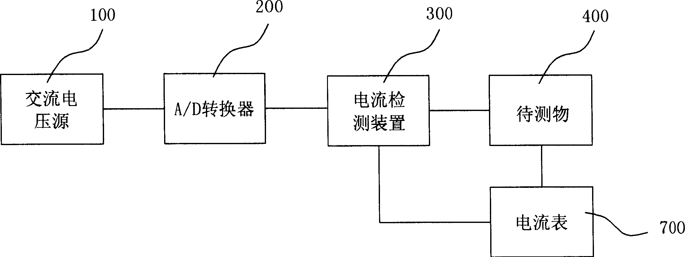
[0016] see image 3 As shown, the current detection of a DUT 400 can be powered by an AC voltage source 100, the AC voltage source 100 is electrically coupled to an A / D converter 200, and the power output from the AC voltage source 100 is passed through the A / D converter After 200, it is converted into a DC voltage source, and the A / D converter 200 is electrically coupled to a current detection device 300, and the current detection device 300 is electrically coupled to the object under test 400 to input power for testing, and the current detection An ammeter 700 is connected in series between the device 300 and the object under test 400 for reading the magnitude of the current flowing through the object under test 400 .

[0017] see Figure 4 As shown, the current detection device 300 is provided with a power input unit 10, the power input unit includes an electrical connector 11 and a diode D2, the electrical connector 11 can be inserted into the A / D converter and form an el...


PUM


Abstract

The disclosed current test device comprises: a power input unit connected to external power, one end of a one-user switch with another end connected to a first output end fit to positive pole of ammeter, and an input end of a voltage comparison unit with output end connected to the first output end that connects to the first end of a first resistance with second end grounded and connected to a second output. This invention simplifies operation.

Description

【Technical field】 [0001] The invention is a current detection device, in particular a current detection device with simplified operation. 【Background technique】 [0002] With the vigorous development of communications and digital technology, electronic products such as mobile phones, smart phones, and personal digital assistants have become indispensable tools in people's daily life. To ensure the quality of electronic products, manufacturers must test the current of electronic products. [0003] Commonly used current detection such as figure 1 and figure 2 As shown, a DC voltage source 100' is electrically coupled to a current detection unit 200' for detecting a current characteristic of an object under test 300'. Wherein, the DC voltage source 100' is respectively provided with a first positive terminal 101' (capable of outputting +4V voltage), a second positive terminal 102' (capable of outputting +5V voltage), and a grounding terminal 103'; The current detection unit...

Claims


Application Information

Patent Timeline
Patent Type & Authority Applications(China)
IPC IPC(8): G01R19/00
Inventor 莫志敏
Owner KUNDA COMP TECHKUSN
Why Eureka
Try Eureka