

Image display method, image coding apparatus, and image decoding apparatus
A technology of image display and image coding, applied in image communication, two-way working system, electrical components, etc., can solve the problems that cannot fully meet the requirements of various standards
- Summary
- Abstract
- Description
- Claims
- Application Information
AI Technical Summary
Problems solved by technology
Method used
Image

Examples
Embodiment approach 1
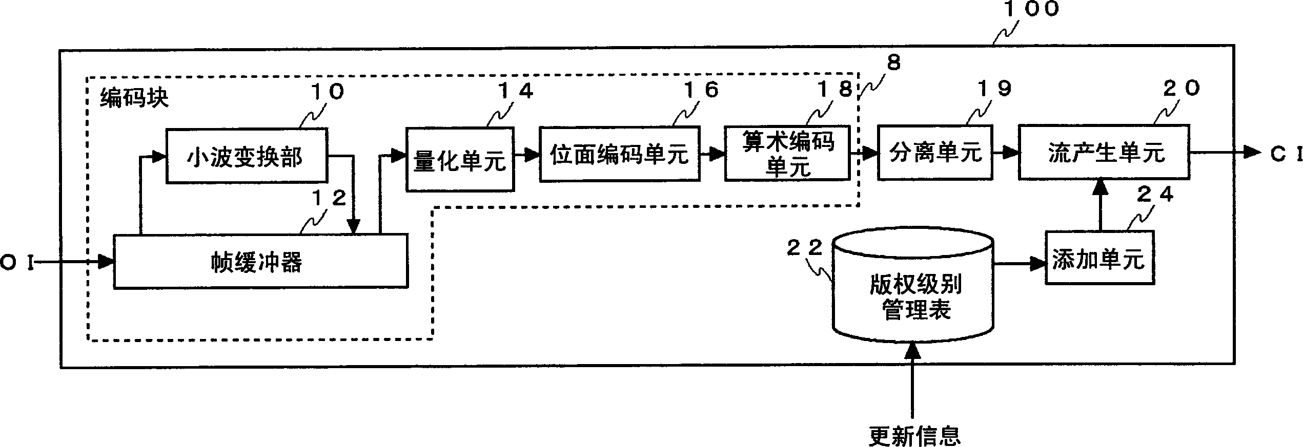
[0048] The present invention realizes an image providing system that is attractive to both an image provider who provides a still image or a moving image and a user who utilizes the image. Embodiment 1 describes an image encoding device 100 that spatially separates image data. For example, the image encoding device 100 uses a DC component as basic data and other frequency components as supplementary data. And, these are allocated separately, and copyright management is performed independently.
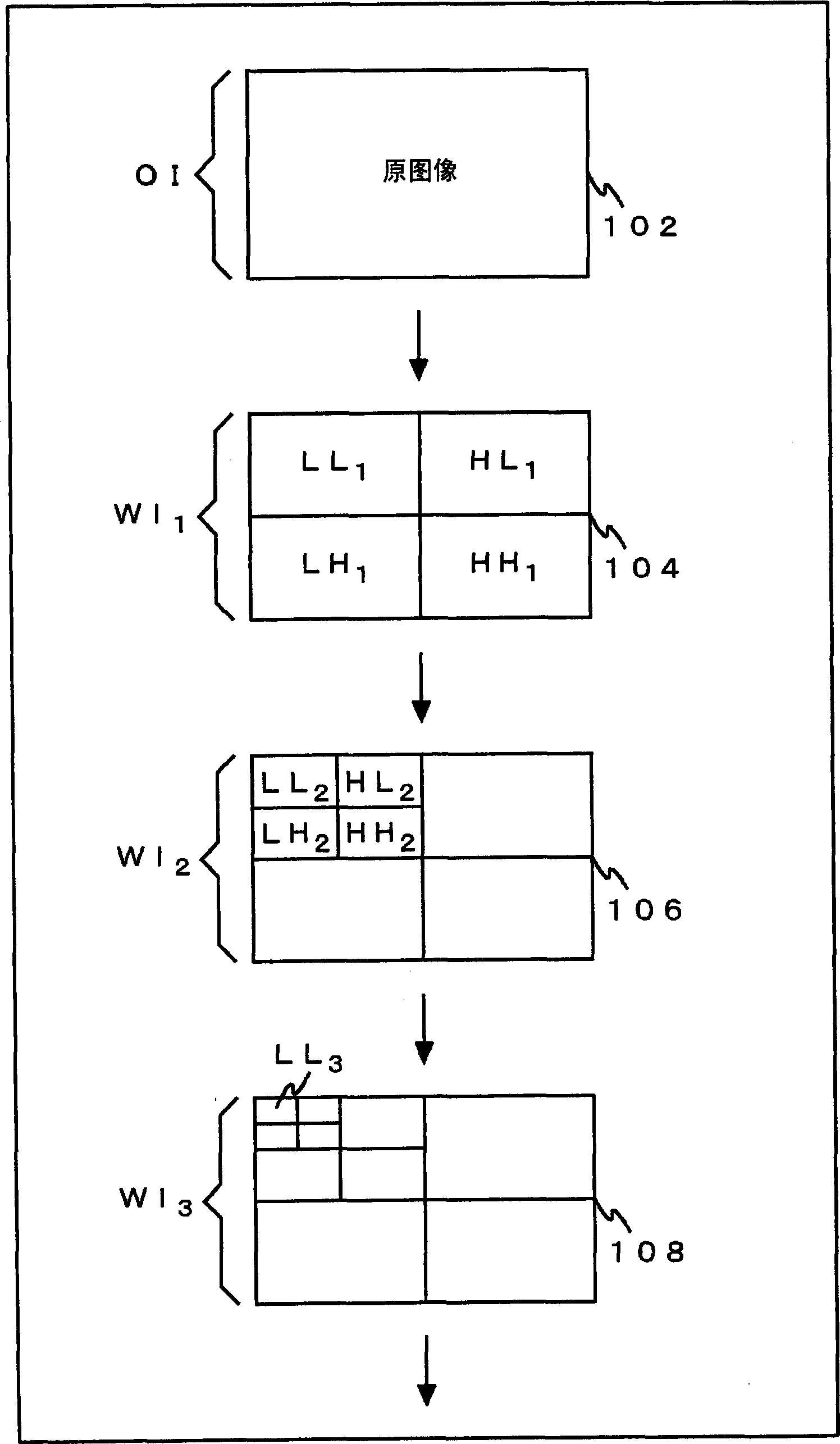
[0049] Embodiment 1 can utilize a technique for generating still images and moving images with different image qualities from a single coded image data stream. As an example, refer to figure 1, simply explain the method of encoding dynamic images according to the Motion-JPEG2000 method. An image encoding device (not shown) continuously encodes each frame of the moving image in frame units, thereby generating an encoded data stream of the moving image. When the encoding process star...
Embodiment approach 2
[0072] Embodiment 2 is an image decoding device 200 that acquires a plurality of encoded image data separated into level units at different timings, and can decode encoded image data obtained by combining these data. Furthermore, if the display unit 38 is mounted, it functions as an image display device.
[0073] Figure 5 The structure of the image decoding device 200 in Embodiment 2 is shown. The image decoding device 200 includes: an acquisition unit 32 , a recording unit 34 , a combining unit 36 and a decoding block 250 . The acquisition unit 32 acquires the coded image data CI separated in units of levels described in the first embodiment. The acquiring unit 32 can also acquire the coded image data CI by downloading from the network, or from a recording medium on which the coded image data CI is recorded. In addition, it can also be obtained from radio waves. The acquisition unit 32 records the acquired coded image data CI in the recording unit 34 . In addition, in...
Embodiment approach 3
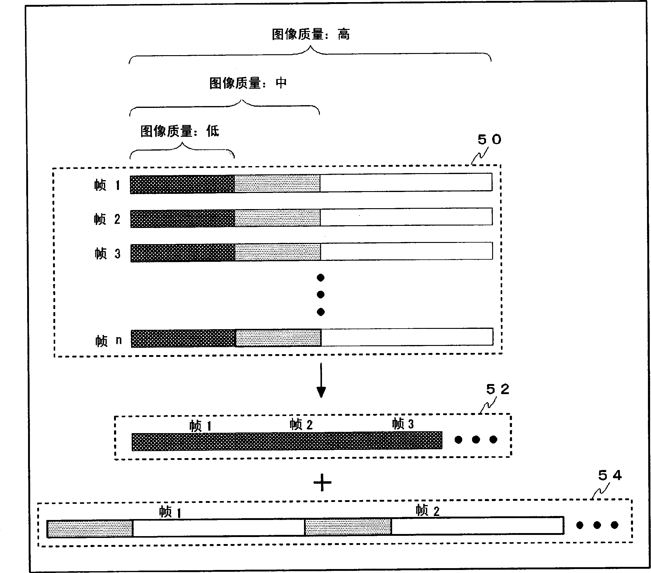
[0086] Embodiment 3 describes the image encoding device 100 for temporally separating image data. The image encoding device 100 uses a part of a plurality of frames constituting a moving image as basic data, and uses other frames as supplementary data. Here, a part of a plurality of frames corresponds to a combination of extracted one slices in the case of extracting one slice out of eight provided slices, or the like. And, assign them separately, and perform independent copyright management.
[0087] The structure and operation of the image encoding device 100 in the third embodiment are basically the same as those in the first embodiment. Next, the differences will be described. In Embodiment 1, an example of encoding a moving image by the Motion-JPEG2000 method was described, and in Embodiment 3, an example of encoding by the MPEG method was described. Since encoding in the MPEG system is a common technique, its detailed description is omitted. according to figure 2 W...
PUM
 Abstract
Description
Claims
Application Information