
Brake prewarning device

A technology of early warning devices and brake sensors, which is applied in signal devices, vehicle components, transportation and packaging, etc., can solve the problems of not reflecting the actual state of brakes, and achieve the effect of avoiding rear-end collision accidents and improving safety

Inactive Publication Date: 2006-11-29
刘苏晋
View PDF1 Cites 4 Cited by
  • Summary
  • Abstract
  • Description
  • Claims
  • Application Information

AI Technical Summary

Problems solved by technology

[0004] However, the above-mentioned patented technology reflects only the braking time of the vehicle in the three stages of the brake light flashing frequency during the braking process, and cannot reflect the actual state of the braking—the decrease in vehicle speed. Therefore, the driver still needs to take corresponding measures based on personal intuition. Braking measures can effectively avoid rear-end collision accidents

Method used


Image

  • Brake prewarning device
  • Brake prewarning device

Examples


Embodiment 1

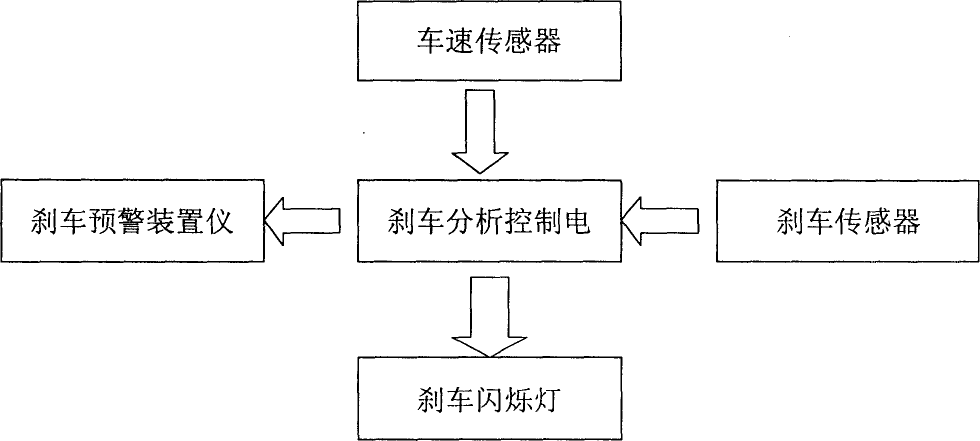
[0016] The brake warning device of this embodiment is as follows: figure 1 As shown, it is mainly composed of a brake sensor, a vehicle speed sensor, a brake analysis control circuit, a brake warning device and a brake flashing light placed at the rear of the vehicle. Wherein, the signal output terminal of the vehicle speed sensor is connected to the signal input terminal of the analysis circuit. The control signal of the analysis circuit is converted into a pulse signal output and connected to the brake flashing light. The signal output terminal of the brake sensor is connected to the working control terminal of the brake analysis control circuit. When the driver brakes, the brake analysis control circuit can be turned on to keep it in the calculation state, receive the input signal of the vehicle speed sensor, and perform analysis and control work.

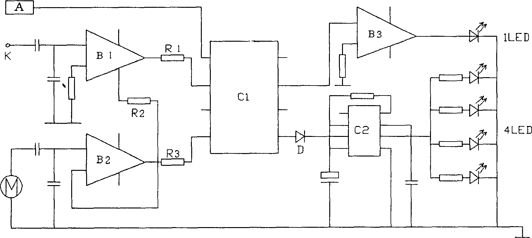
[0017] Brake analysis control circuit see figure 2 , where the analysis circuit is mainly composed of AND gate circuit B2 a...


PUM


Abstract

An improved braking pre-warning device is composed of the flash tail lamps, braking sensor, speed sensor and the analyzing-controlling circuit for braking, which consists of analyzer and pulse signal generator. Said analyzer has a CPU for analyzing the braking state and controlling the width of pulse signal and in turn the turn-on time of flash tail lamp.

Description

technical field [0001] The invention relates to an early warning device when a vehicle brakes, in particular to an improvement of a brake early warning device, which belongs to the technical field of vehicle accessories. Background technique [0002] As we all know, when the vehicle is braking, the brake lights at the rear of the vehicle are always on, which can serve as a warning to subsequent vehicles to slow down and prevent rear-end collisions. With the rapid extension of the expressway and the continuous increase of vehicle speed, the shortcomings of this early warning method have become obvious, that is, the driver of the vehicle behind cannot perceive the speed of braking of the vehicle in front and the length of the braking time according to the status of the brake lights. [0003] For this reason, the Chinese invention patent that the application number is 93108373.7, and the application date is 1993.07.16 discloses a kind of brake light warning device with multi-st...

Claims


Application Information

Patent Timeline
Patent Type & Authority Applications(China)
IPC IPC(8): B60Q1/54
Inventor 刘苏晋
Owner 刘苏晋
Learn More