Tie bar installation in use for suspended ceiling of building

A tie rod device and building technology, applied in the direction of building structures, buildings, building components, etc., can solve the problems of insufficient connection, inability to apply suspended ceilings, inconvenient disassembly and disassembly, etc., and achieve the advantages of easy processing, simple structure and convenient installation Effect

Active Publication Date: 2006-12-06
上海浦飞尔金属吊顶有限公司
View PDF2 Cites 5 Cited by
  • Summary
  • Abstract
  • Description
  • Claims
  • Application Information

AI Technical Summary

Problems solved by technology

[0004] There are obvious deficiencies in this utility model, and its application is too narrow, such as it cannot be applied to the suspended ceiling of large or larger buildings in modern municipal construction; The installation angle between the room and the decorative panel is three-dimensional adjustable

Method used


Image

  • Tie bar installation in use for suspended ceiling of building
  • Tie bar installation in use for suspended ceiling of building
  • Tie bar installation in use for suspended ceiling of building

Examples


Embodiment Construction

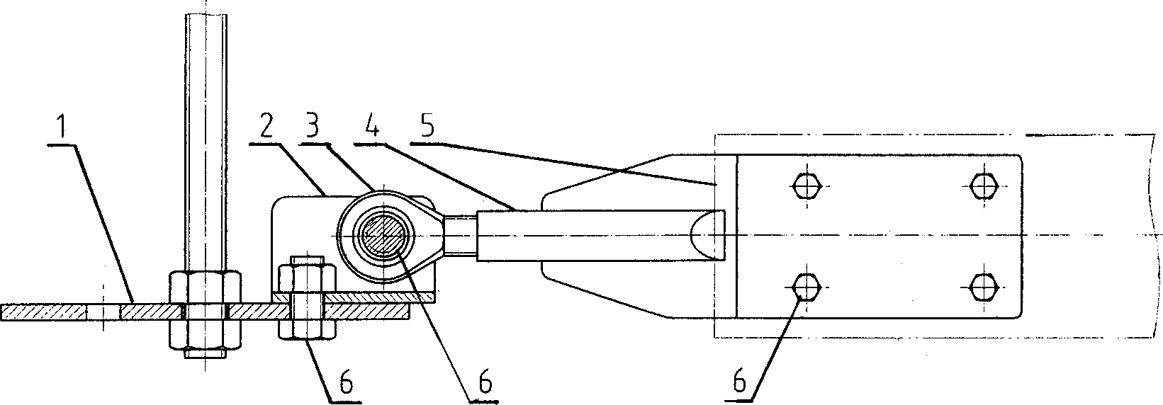
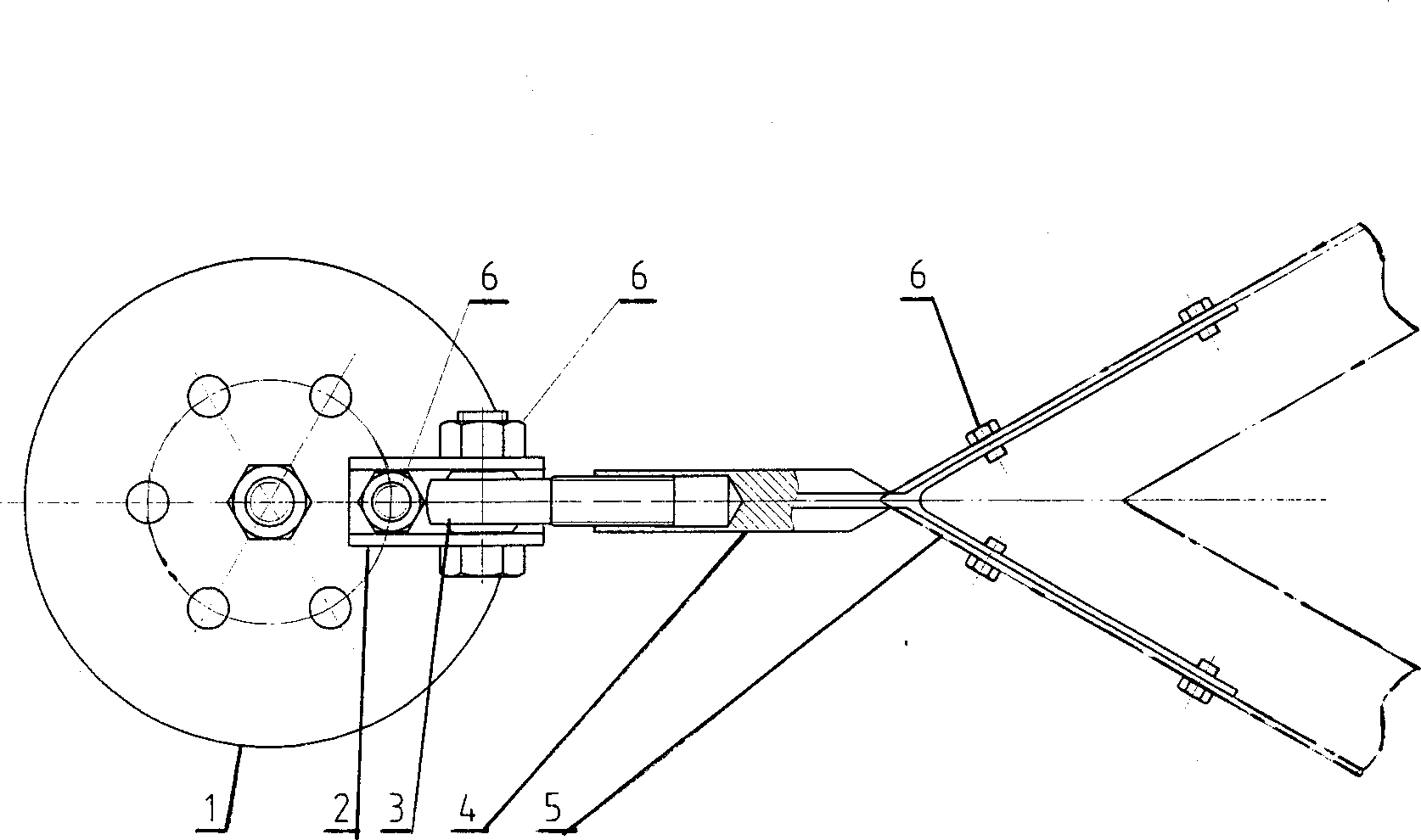
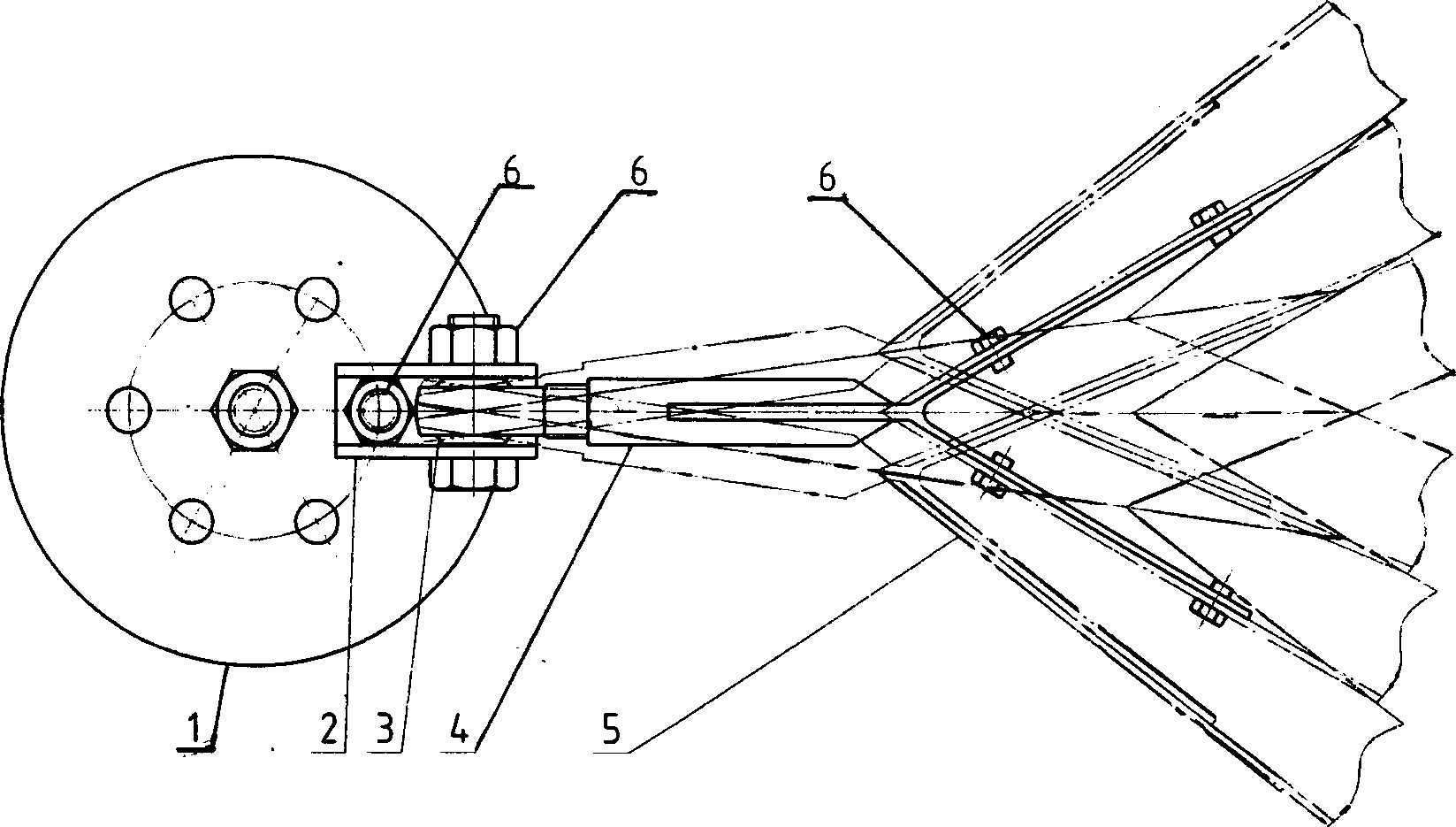
[0017] Such as figure 1 , 2 As shown, the present invention comprises: base 1, support 2, universal joint pull rod 3, connecting plate 4, keel 5, bolt 6, and base 1 is provided with positioning hole, and support 2 bottom surface is provided with positioning hole, supports by 6 bolts 2 Positioning and fixing on the plane of the base 1, one end of the universal joint rod 3 is connected with the connection plate 4, the other end is positioned between the two sides of the bracket 2 through bolts, the connection plate 4 is connected and fixed with the keel 5, and the keel 5 is connected with the ceiling decoration board fixed.

[0018] Such as Figure 5 As shown, the base 1 is made into a circle, and can be made into various shapes according to design requirements, such as: triangle, quadrangle, pentagon, or ellipse, or polygon.

[0019] Such as figure 2 , 3 As shown in , 5, a number of corresponding positioning holes are evenly distributed on the plane of the base 1 .

[00...


PUM


Abstract

A drawbar used on hang ceiling of building is prepared as setting a positioning hole on base and on support bottom surface, fixing support positioning on base plane by bolt, connecting one end of universal-joint drawbar with connection plate and positioning another end of said drawbar on place between two sides of support, firm-joining connection plate with keel and utilizing keel to fix dalles of hang ceiling.

Description

technical field [0001] The invention relates to a device in the technical field of construction, in particular to a tie rod device used for a suspended ceiling of a building. Background technique [0002] Most of the existing suspended ceilings use keel frames, strip or flat decorative panels and various connectors to connect the decorative panels to the keel frames through plug-in or embedded, and are mostly used for general architectural decoration and home decoration, such as: Among the existing technologies, there is a utility model whose technical name is "ceiling hoisting structure", and the patent application number is CN93229510.X. The lower end of the frame is provided with inwardly bent hooks, and both sides of the upper end of the keel are provided with downwardly bent hooks, and the hanger hook is hung in the downwardly bent hooks of the keel. The upper part of the beam keel is provided with supporting ribs, and the supporting ribs are placed horizontally on the...

Claims


Application Information

Patent Timeline
Patent Type & Authority Applications(China)
IPC IPC(8): E04B9/06
Inventor 康惟宁汤桂荣
Owner 上海浦飞尔金属吊顶有限公司
Why Eureka
Try Eureka