Backlight module, and plane lamp

A technology of backlight module and flat lamp, which is applied in the direction of light source fixing, lighting device, and components of lighting device, etc., can solve the problems of high manufacturing cost and complicated assembly process of the backlight module 1, so as to shorten the manufacturing process time and save the cost of parts. , the effect of improving dimensional accuracy

Inactive Publication Date: 2006-12-06
AU OPTRONICS CORP
View PDF0 Cites 5 Cited by
  • Summary
  • Abstract
  • Description
  • Claims
  • Application Information

AI Technical Summary

Problems solved by technology

Therefore, the manufacturing cost of the backlight module 1 is relatively high, and the assembly process is relatively complicated.

Method used


Image

  • Backlight module, and plane lamp
  • Backlight module, and plane lamp
  • Backlight module, and plane lamp

Examples


Embodiment Construction

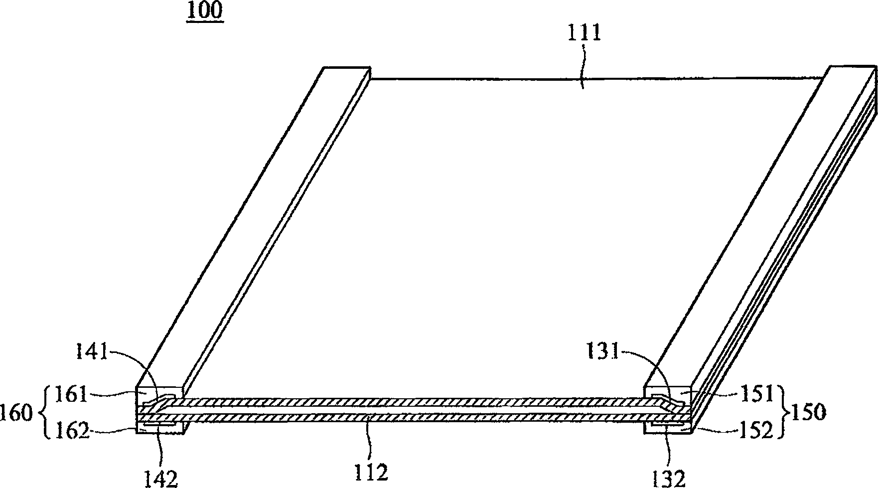
[0031] refer to Figure 2a , Figure 2b , which shows the flat lamp 100 of the present invention, including a first substrate 111, a second substrate 112, a first outer upper electrode 131, a first outer lower electrode 132, a second outer upper electrode 141, a second outer lower electrode 142, a first outer electrode A packaging material 150 and a second packaging material 160 . The first substrate 111 is opposite to the second substrate 112, and a sealing material (not shown) is applied around the inner surface sides of the first substrate 111 and the second substrate 112 to seal the first substrate 111 and the second substrate 112. the second substrate 112 . The first outer upper electrode 131 is disposed on the outer surface of the first substrate 111 and is close to a first side of the planar lamp 100 . The first outer lower electrode 132 is disposed on the outer surface of the second substrate 112 , close to the first side of the planar lamp 100 , corresponding to an...


PUM


Abstract

The present invention relates to a plane lamp. It includes first baseplate, second baseplate, first external electrode, second external electrode, first packaging material and second packaging material. The first baseplate is superimposed on second baseplate, first external electrode is placed on the external surface of said first baseplate and second baseplate, and is close to a first side of said plane lamp, said second external electrode is placed on the external surface of said first baseplate and said second baseplate, and is close to a second side of said plane lamp. Said first external electrode is covered with said first packaging material and said second external electrode is covered with said second packaging material.

Description

technical field [0001] The present invention relates to a plane lamp, in particular to a plane lamp applied to a backlight module. Background technique [0002] refer to Figure 1a , which shows a traditional backlight module 1 , including a planar lamp 10 , a housing 13 , a plurality of supporting components 14 and a plurality of fixing components 15 . The planar lamp 10 includes an upper substrate 11 and a lower substrate 12 . The upper substrate 11 overlaps with the lower substrate 12 . External electrodes 16 are provided on the outer surface of the lower substrate 12 . The external electrodes 16 contact the support 14 and transfer the heat of the planar lamp 10 directly to the support 14 . Please refer to Figure 1b , which is a detailed structural diagram of a support member 14 made of a traditional plastic material. In addition to the structure of the supporting member 14 must include the locking portion 18 , a heat-resistant insulating sheet 17 needs to be dispos...

Claims


Application Information

Patent Timeline
Patent Type & Authority Applications(China)
IPC IPC(8): F21V17/00
Inventor 林佑撰
Owner AU OPTRONICS CORP
Why Eureka
Try Eureka