Power source for vehicle and cooling structure of cell

A technology for power supply devices and vehicles, which is applied in the direction of electric power devices, vehicle energy storage, secondary batteries, etc., and can solve problems such as difficult air-guided power supply devices

Inactive Publication Date: 2006-12-06
HONDA MOTOR CO LTD
View PDF4 Cites 59 Cited by
  • Summary
  • Abstract
  • Description
  • Claims
  • Application Information

AI Technical Summary

Problems solved by technology

[0009] In this way, even if it is assumed that the air in the vehicle compartment is used as cooling air for the battery of the power supply unit, when the power supply unit is arranged in the lu

Method used


Image

  • Power source for vehicle and cooling structure of cell
  • Power source for vehicle and cooling structure of cell
  • Power source for vehicle and cooling structure of cell

Examples


no. 1 approach

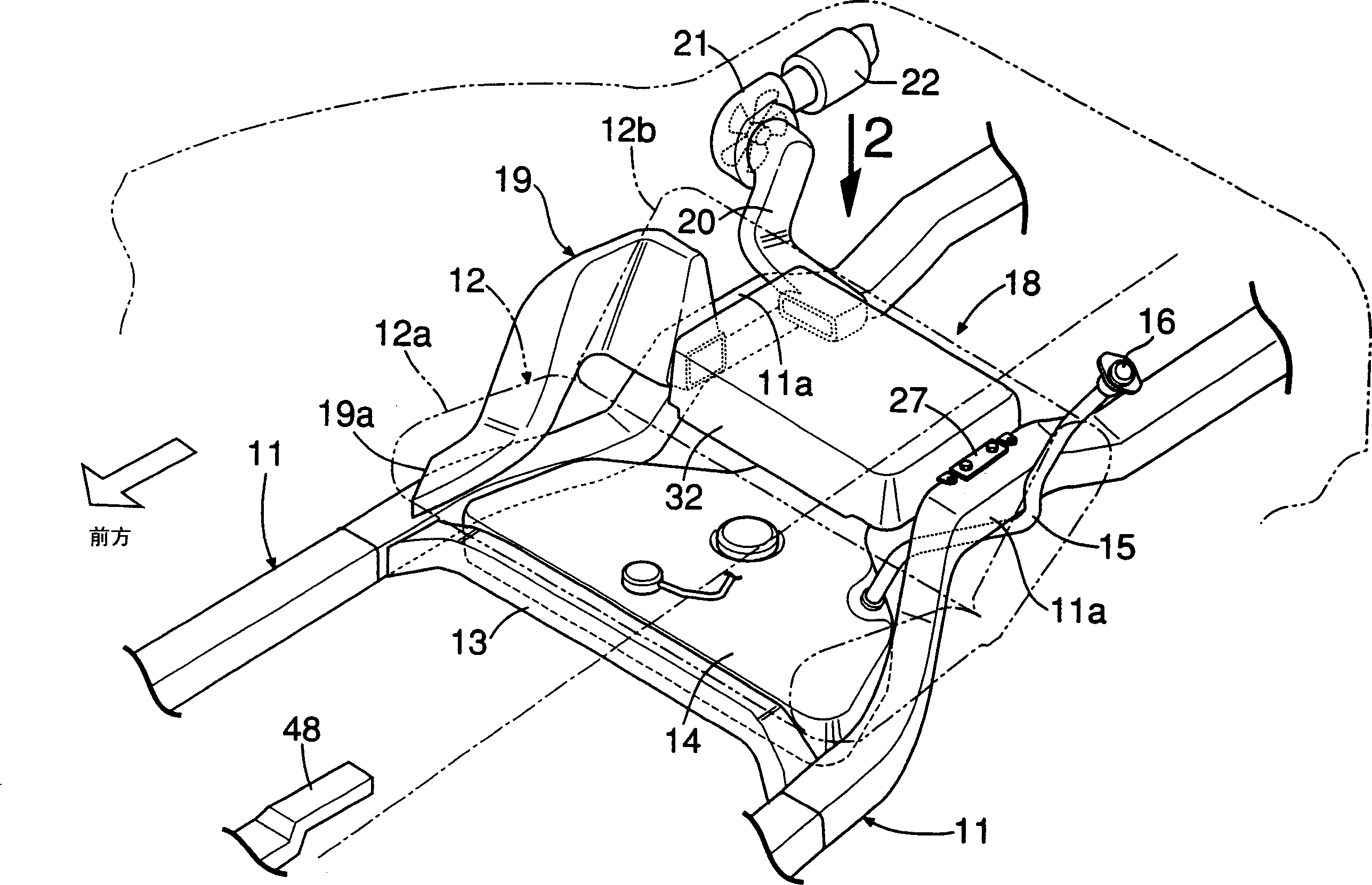
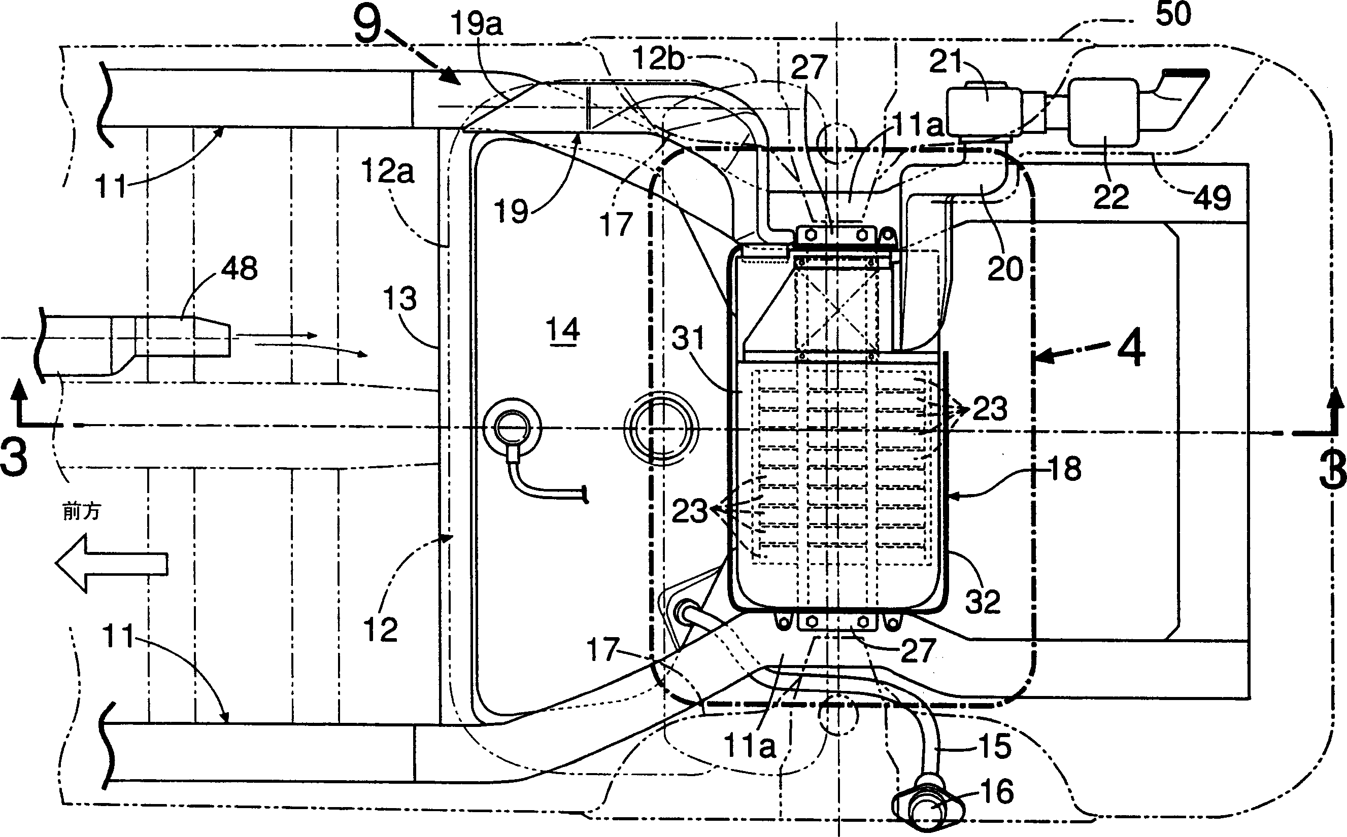
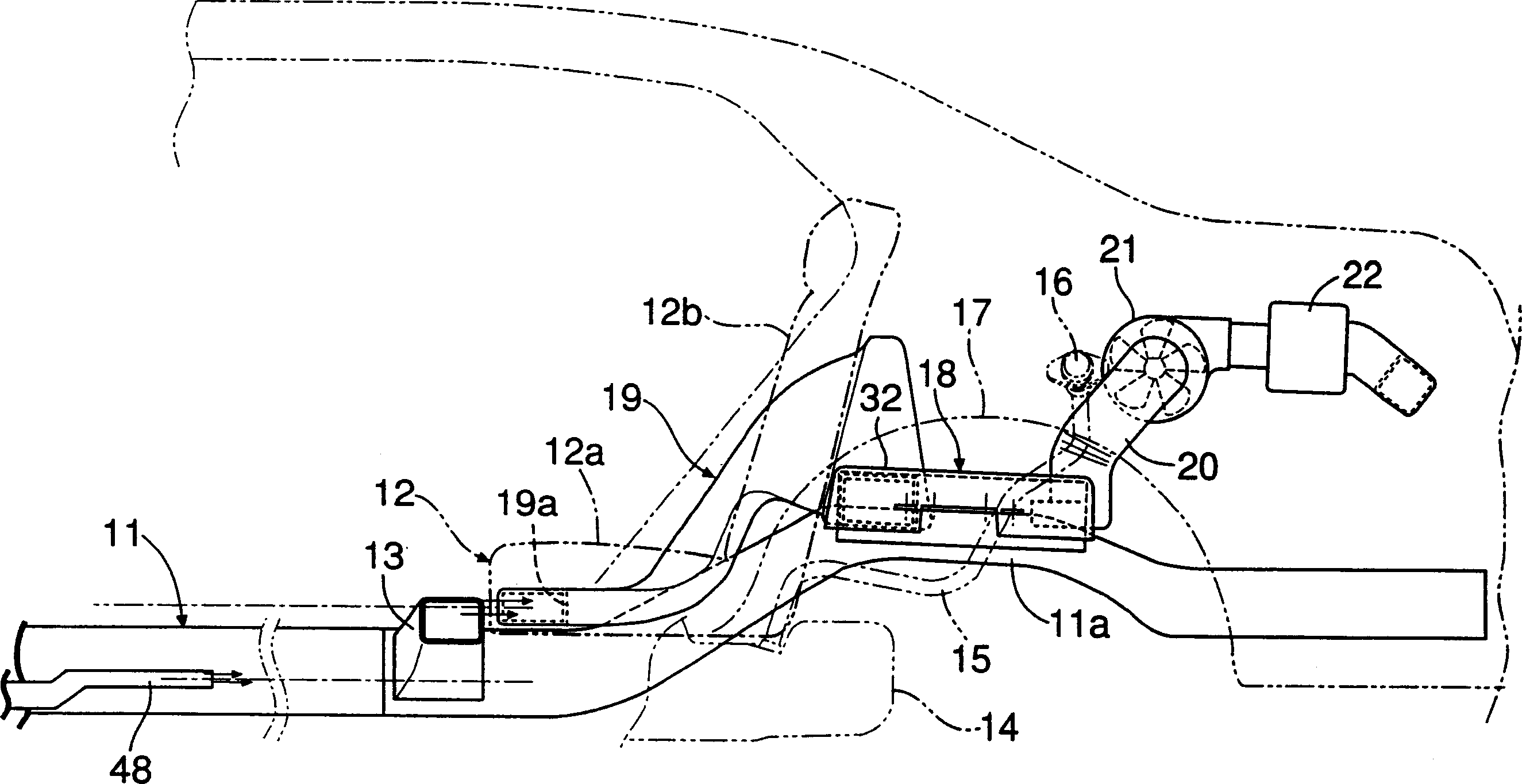
[0071] Such as Figure 1 ~ Figure 4 As shown, a hybrid vehicle equipped with an engine and a motor / generator as a driving power source has a pair of side frames 11 and 11 disposed in the front and rear direction of the vehicle body on the left and right sides of the vehicle body. 12 , left and right side frames 11 , 11 are connected via a beam 13 to the front lower surface of the seat cushion 12 a. In the space surrounded by the left and right side frames 11, 11, the cross member 13, and the underside of the seat cushion 12a, a fuel tank 14 is arranged, and a supply pipe 15 extending rearward and upward from the left end of the fuel tank 14 is provided. The upper end is provided with a filler port 16. The left and right side frames 11, 11 are provided with curved portions 11a, 11a bent upward at positions corresponding to the wheel housings 17, 17, and between the vertices of the curved portions 11a, 11a, a motor / generator is connected. The left and right ends of the battery...


PUM


Abstract

The invention discloses a vehicular power supply device. A battery box 18 for accommodating a battery is mounted in a deviated manner to the left side of a vehicle body between right and left side frames 11 extending in the longitudinal direction of the vehicle body, and an intake duct 19 and an exhaust duct 20 of cooling air for cooling the battery are connected to an end of the battery box 18 on the right side of the vehicle body. Thus, the battery can be protected from shocks in the side impact by the right and left side frames 11, and at the same time, a space for arranging the intake duct 19 and the exhaust duct 20 can be ensured while ensuring the maximum capacity of the battery box 18. In addition, since right and left ends of the battery box 18 are connected to the right and left side frames 11, the battery box 18 can be firmly mounted on the vehicle body, and the rigidity of the right and left side frames 11 can be enhanced by the battery box 18.

Description

technical field [0001] The present invention relates to a power supply device for a vehicle that supplies electric power from a battery housed in a battery box to an electric motor that drives the vehicle, and battery cooling that cools the battery with cooling air flowing through a cooling passage provided in the battery box structure. Background technique [0002] From Japanese Patent Application Laid-Open No. 2003-317813 and Japanese Patent Laid-Open No. 2005-71759, it is known that a battery box containing a battery that supplies power to a motor / generator (generator) of a hybrid vehicle is arranged in front of the luggage room behind the rear seat. Connect the intake duct and exhaust duct for supplying / discharging the cooling air for cooling the battery to the left and right sides of the battery box. [0003] It is necessary to protect the battery box from damage in the event of a side collision in the hybrid vehicle concerned, but there is also the problem that if spe...

Claims


Application Information

Patent Timeline
IPC IPC(8): H01M10/50H01M2/10B60K1/04B60L11/18B60H1/22H01M10/613H01M10/625H01M10/6563H01M10/6566H01M50/242H01M50/244H01M50/249
CPCY02E60/12Y02T10/7005Y02E60/10
Inventor 小池荣治武富春美大矢聪义大熊香苗佐藤诚一
Owner HONDA MOTOR CO LTD
Why Eureka
Try Eureka