Method for mounting fin onto heat pipe

A technology of fins and heat pipes, which is applied in the field of increasing the contact area between fins, can solve the problems of small contact area, low heat conduction, and difficult heat circulation, etc., and achieve the effect of increasing contact area, rapid and uniform heat dissipation

Inactive Publication Date: 2006-12-13
AMA PRECISION INC
View PDF0 Cites 0 Cited by
  • Summary
  • Abstract
  • Description
  • Claims
  • Application Information

AI Technical Summary

Problems solved by technology

[0002] The existing method of installing the fins on the heat pipe usually forms a ring wall on the outer edge of the through hole of the fin, and then makes the heat pipe pass through the through hole to complete the installation operation; however, after the fins are stacked, Only rely on the top edge of the ring wall to contact each other, resulting in a small contact area between the fins, or even no contact at all, so the heat conduction between the fins is low, which can only meet the heat dissipation effect of the cooling end of the heat pipe alone, but cannot be effective. Share the heat of the overheated fins in each fin, resulting in difficult heat flow and poor heat dissipation effect

Method used


Image

  • Method for mounting fin onto heat pipe
  • Method for mounting fin onto heat pipe
  • Method for mounting fin onto heat pipe

Examples


Embodiment Construction

[0026] The features and technical content of the present invention will be described in detail below in conjunction with the accompanying drawings. The drawings and descriptions are provided for the purpose of illustration only and do not limit the scope of the invention in any way.

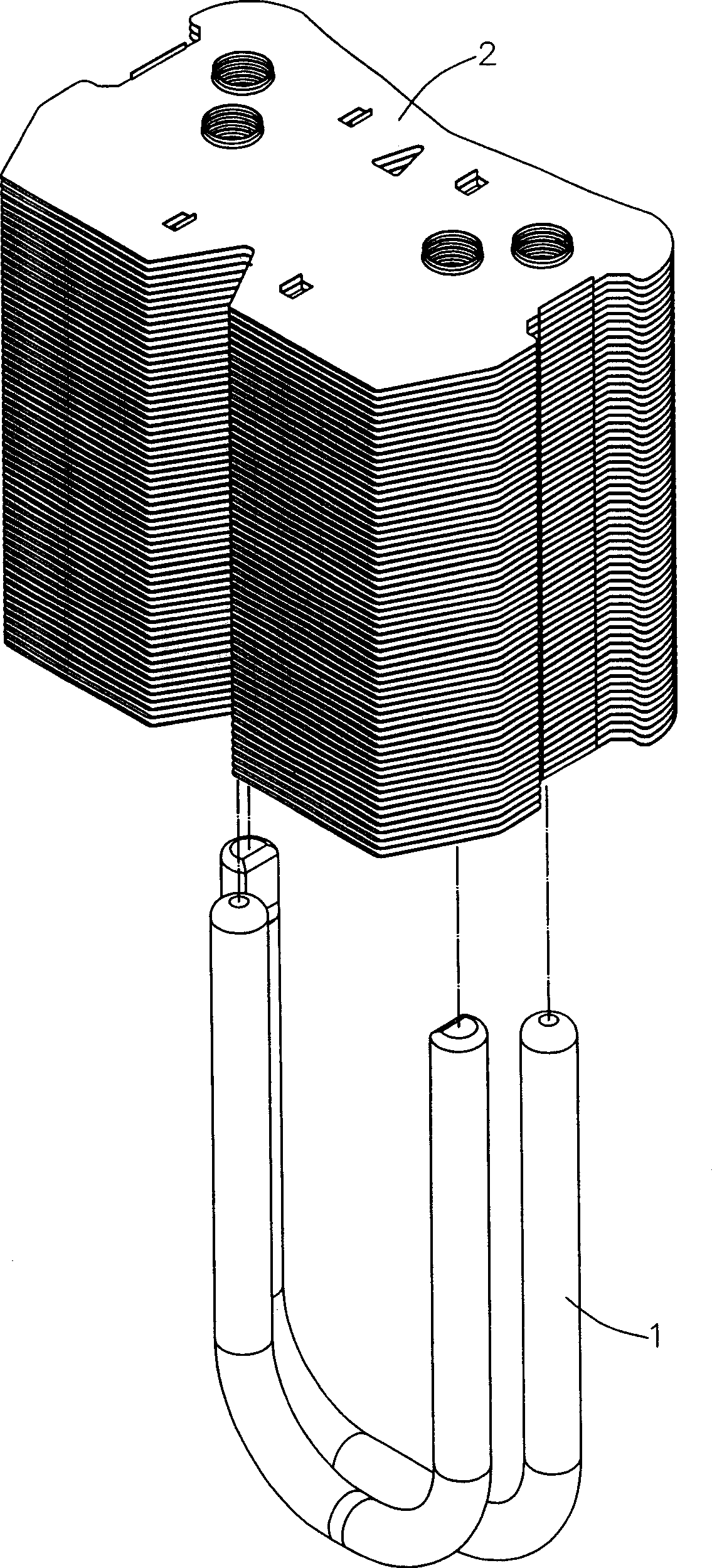
[0027] figure 1 Shown is a three-dimensional exploded view of the heat pipe and fins of the present invention. The present invention provides a method for installing fins on heat pipes, which is used to install thin fins 2 with a thickness of less than 0.2mm on heat pipes 1, so as to meet the heat dissipation requirements of the cooling end of heat pipes 1, and improve heat pipe 1 and each fin. The bonding density between sheets 2 reduces the generation of voids.

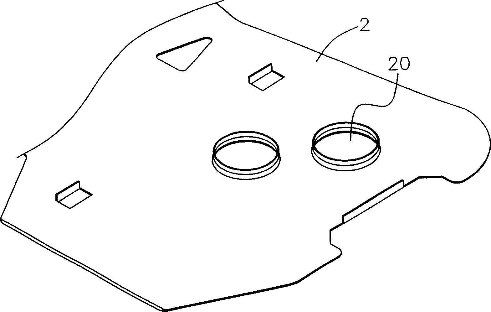
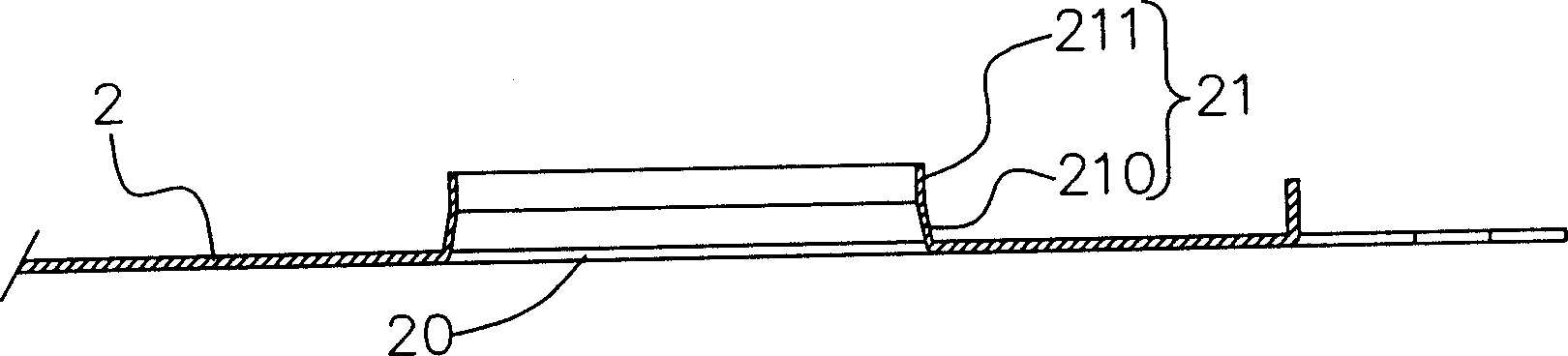
[0028] Such as figure 2 , image 3 and Figure 4 As shown, through holes 20 are first punched on each fin 2 , and the number of through holes 20 on each fin 2 depends on its matching with the heat pipe 1 . While punching through...


PUM


Abstract

The invention relates to a method for mounting fins on the heat pipe, which comprises punching through hole on each fin, and drawing out the annular wall with reduced diameter from the edge of through hole; stacking the fins; matching the heat pipe and the fins, to be inserted from the wider annular wall into the through hole of each fin; then functioning the fins at reversed direction, to embed the annular wall of each fin into the space between the annular wall of front fin and the surface of heat pipe, to be compressed on the heat pipe; therefore, each fin can be contacted to increase the contact area, and make the contact between the annular and the heat pipe more compact, to avoid space and meet the heat emission demand of cooling end of heat pipe.

Description

technical field [0001] The invention relates to a method for installing fins on heat pipes, in particular to a method for installing thin fins on heat pipes and increasing the contact area between the fins. Background technique [0002] The existing method of installing the fins on the heat pipe usually forms a ring wall on the outer edge of the through hole of the fin, and then makes the heat pipe pass through the through hole to complete the installation operation; however, after the fins are stacked, Only rely on the top edge of the ring wall to contact each other, resulting in a small contact area between the fins, or even no contact at all, so the heat conduction between the fins is low, which can only meet the heat dissipation effect of the cooling end of the heat pipe alone, but cannot be effective. Share the heat of the overheated fins among the fins, resulting in difficult heat flow and poor heat dissipation effect. [0003] In view of this, in order to improve and...

Claims


Application Information

Patent Timeline
Patent Type & Authority Applications(China)
IPC IPC(8): F28D15/02
Inventor 陈国星林暄智
Owner AMA PRECISION INC
Why Eureka
Try Eureka