A matching cooling tank structure based on stamping die

A stamping die and cooling tank technology, which is applied in the field of matching cooling tank structure, can solve the problems of poor cooling effect, single cooling method, slow cooling speed, etc., achieve rapid and uniform heat dissipation, improve heat dissipation efficiency, and increase heat dissipation effect.

Active Publication Date: 2021-05-07
株洲爱德冲压产品制造有限公司
View PDF10 Cites 0 Cited by
  • Summary
  • Abstract
  • Description
  • Claims
  • Application Information

AI Technical Summary

Problems solved by technology

[0007] The purpose of the present invention is to provide a matching cooling tank structure based on stamping dies to solve the problem that the structural design proposed in the above background technology is relatively simple, and most of them open several circular grooves for cooling water to pass through for cooling. The cooling method is relatively simple, the cooling effect is poor, and the cooling speed is slow

Method used


Image

  • A matching cooling tank structure based on stamping die
  • A matching cooling tank structure based on stamping die
  • A matching cooling tank structure based on stamping die

Examples


Embodiment

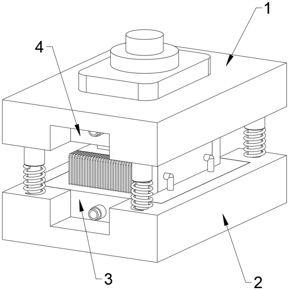
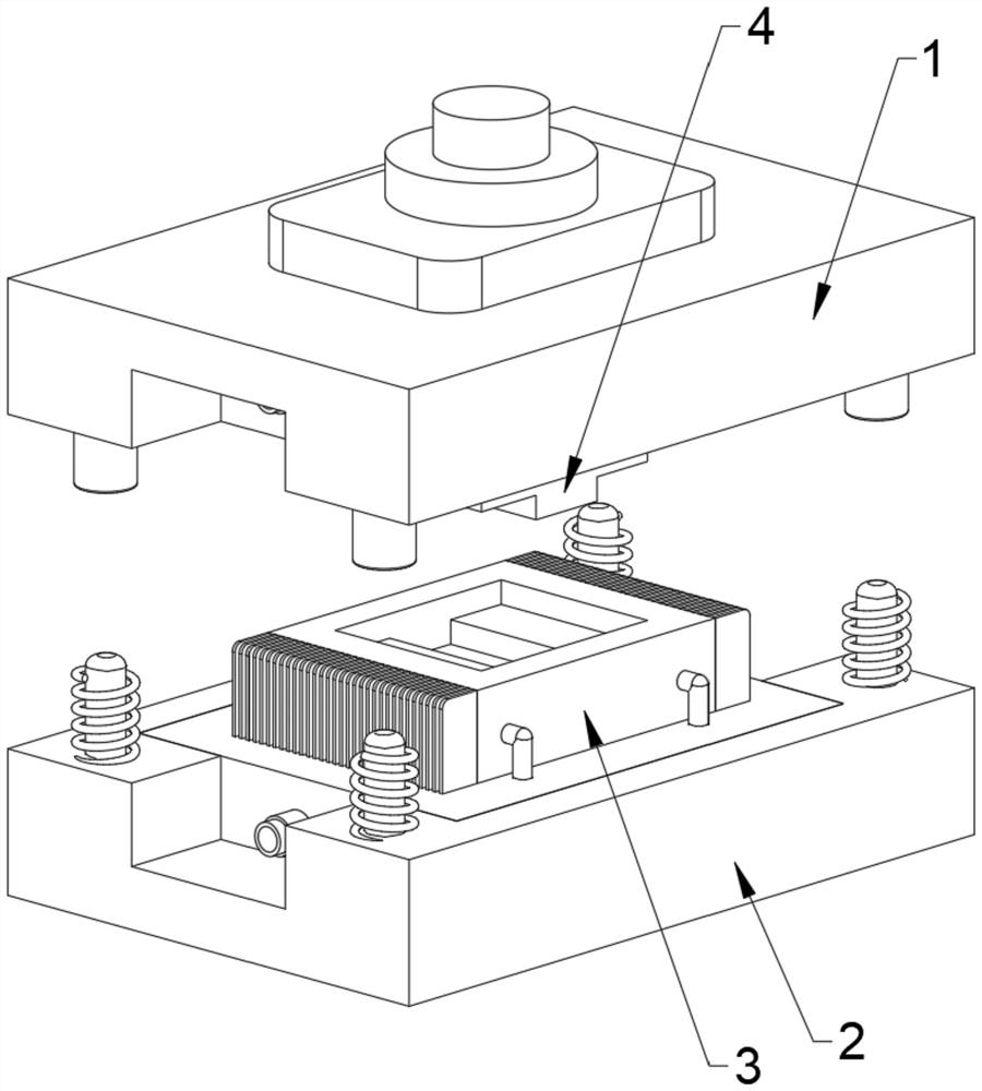
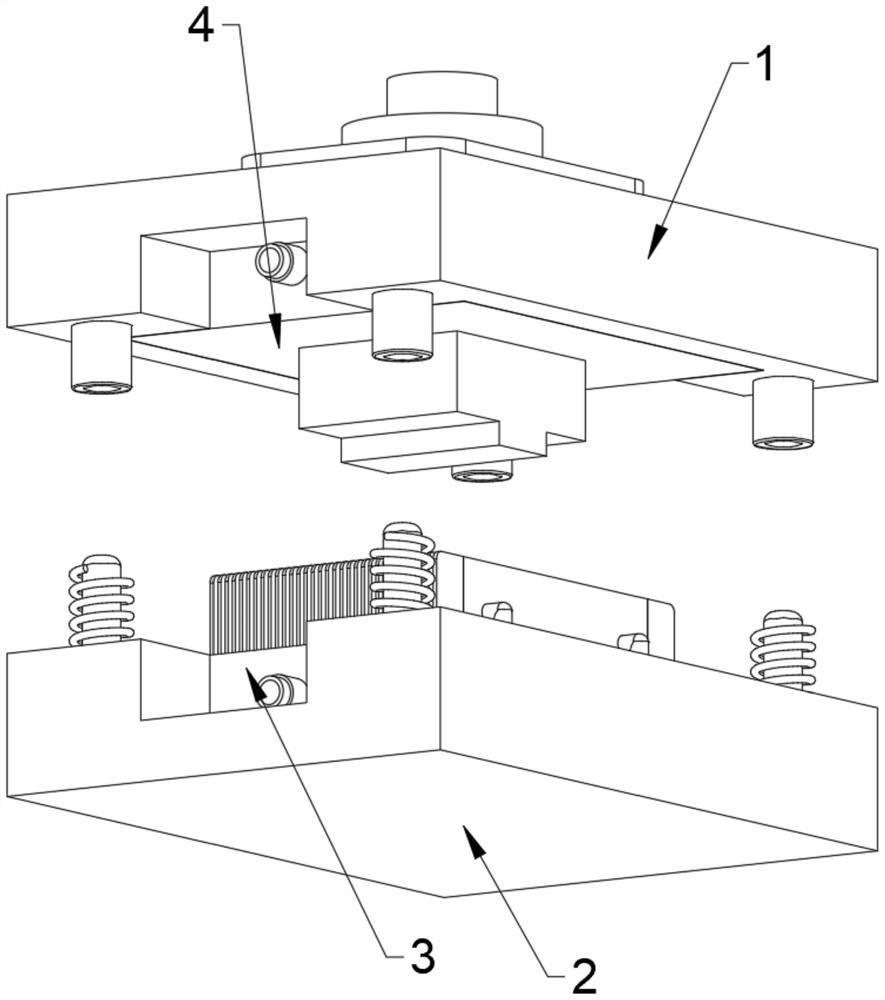
[0041] as attached figure 1 to attach Figure 10 Shown:

[0042] The present invention provides a matching cooling tank structure based on stamping dies, including: upper die fixing plate 1, lower die fixing plate 2, stamping lower die 3, cooling lower die plate 301, cooling water circulation pipe 302, and lower die cooling fins 303 , the lower mold core 304, the supporting heat dissipation column 305, the circulating cooling water chamber 306, the stamping upper mold 4, the upper mold core 401, the upper mold cooling plate 402, the mold core supporting heat dissipation plate 403 and the cooling water access pipe 5; The inner side bolt of the upper die fixing plate 1 is fixedly equipped with a stamping upper die 4, and the stamping upper die 4 is composed of an upper die core 401, an upper die cooling plate 402 and a die core supporting cooling plate 403; the lower die is fixed The inner side of the plate 2 is fixed with a lower stamping die 3, and the lower stamping die 3 i...


PUM


Abstract

A matching cooling tank structure based on stamping dies, comprising an upper die fixing plate, a lower die fixing plate and a stamping lower die; the inner side bolts of the upper die fixing plate are fixedly equipped with a stamping upper die, and the stamping upper die is formed by the upper die The mold core, the upper mold cooling plate and the mold core supporting heat dissipation plate are composed of three parts; the inner bolt of the lower mold fixing plate is fixed with a stamping lower mold; the upper mold core and the lower mold core are designed correspondingly; The upper mold fixing plate is correspondingly installed on the upper side of the lower mold fixing plate, and the upper mold fixing plate and the lower mold fixing plate are slidably connected through the guide column. The inside of the cooling lower template provided by the matching cooling tank structure based on the stamping die is provided with a cooling water chamber, and the left and right sides of the cooling lower template are connected with cooling water inlet pipes, and the cooling water inlet pipes are connected to the outside The cooling device is connected to facilitate the rapid injection of cooling water into the inner cavity of the cooling lower formwork through the cooling water inlet pipe, thereby realizing the rapid cooling operation of the lower stamping die.

Description

technical field [0001] The invention relates to the technical field of mold equipment, in particular to a matching cooling groove structure based on a stamping mold. Background technique [0002] Stamping die is a special process equipment for processing materials (metal or non-metal) into parts (or semi-finished products) in cold stamping processing, called cold stamping die (commonly known as cold stamping die). Stamping is a pressure processing method that uses a mold installed on a press to apply pressure to the material at room temperature to cause separation or plastic deformation to obtain the required parts; the stamping mold generates a lot of heat during use , if the heat can not be fast, it may damage the stamping die and stamping parts, so it is necessary to install a cooling device on the stamping die. [0003] After patent retrieval, the existing patent No. 201810449518.1 discloses a cast iron stamping die with shock absorption and rapid cooling functions, inc...

Claims


Application Information

Patent Timeline
Patent Type & Authority Patents(China)
IPC IPC(8): B21D37/12B21D37/16
CPCB21D37/12B21D37/16
Inventor 陈冲
Owner 株洲爱德冲压产品制造有限公司
Why Eureka
Try Eureka