Production of component parts by metal injection moulding (mim)

a technology of metal injection molding and component parts, which is applied in the direction of metal-working apparatus, transportation and packaging, etc., can solve the problems of high cost, poor machinability, and high degree of tool wear, and achieve the effect of reducing the debinding time and affecting the stabilization of the component body

Inactive Publication Date: 2004-07-29
FORSCHUNGSZENTRUM JULICH GMBH
View PDF4 Cites 11 Cited by
  • Summary
  • Abstract
  • Description
  • Claims
  • Application Information

AI Technical Summary

Benefits of technology

[0015] An advantageous variant of the method is directed to the use of a two-component binder on a wax basis, especially a two-component binder of an amide wax and a polyolefin wax in a suitable composition. The amide wax influences the flow characteristics of the feed stock and serves for the plastification thereof while the polyolefin serves for stabilization of the feed stock and contributes to the component part which is obtainable therefrom. Injection molding masses with viscosities of about 5 to 30 Pa.s can be injected. The very good flowability of the mass enables a rapid injection as well as a cavity-free and defect-free filling of even complex mold cavities with undercuts.
[0036] Through the capillary forces, the melted wax is sucked out of the component body. The use of the filter paper supports this effect and protects the component parts against adhesion of the wicking material used. The binder system is so constructed that after the predebinding process, the residual plastifying component is driven out or evaporated. A minor residual binder proportion between the individual particles ensures the shape stability of the green body until this residual binder is driven off by the combined debinding / sintering step. The component part, after the wicking process, can be handled and can be removed from the sand bed for the sintering and can be placed upon ZrO.sub.2 sintering supports for the sintering process.

Problems solved by technology

The shape was conventionally imparted by the mechanical machining of castings of NiTi material made by melt metallurgy and the method has been limited in that the alloys in the martensitic state have a high yield strength and thus a poor machinability.
As a consequence the after-machining of melt metallurgy fabricated component parts has been possible only with a high expenditure of time and a high degree of tool wear.
The use of the metal injection molding process also for NiTi shape memory alloys has been a problem since apart from economical production rates, all of the small impurity contents required in the end product for the shape memory properties had to be insured.
The difficulties of fabricating NiTi component parts by metal injection molding (MIM) is that the contents of oxygen and carbon must be held as low as possible.
High impurity contents give rise to a reduced sintering activity of the metal powder and diminish the properties of the material in the sintered component part (for example by embrittlement).

Method used


Image

  • Production of component parts by metal injection moulding (mim)
  • Production of component parts by metal injection moulding (mim)

Examples


example 1

[0039]

1 1400 g NiTi - powder 64.4 g Amide wax 42.9 g Polyolefin

[0040] Total binder proportion: 7.12% by weight=34 volume %.

example 2

[0041]

2 1800 g NiTi - powder 64.4 g Amide wax 42.9 g Polyolefin

[0042] Total binder proportion: 5.63% by weight=28 volume %.

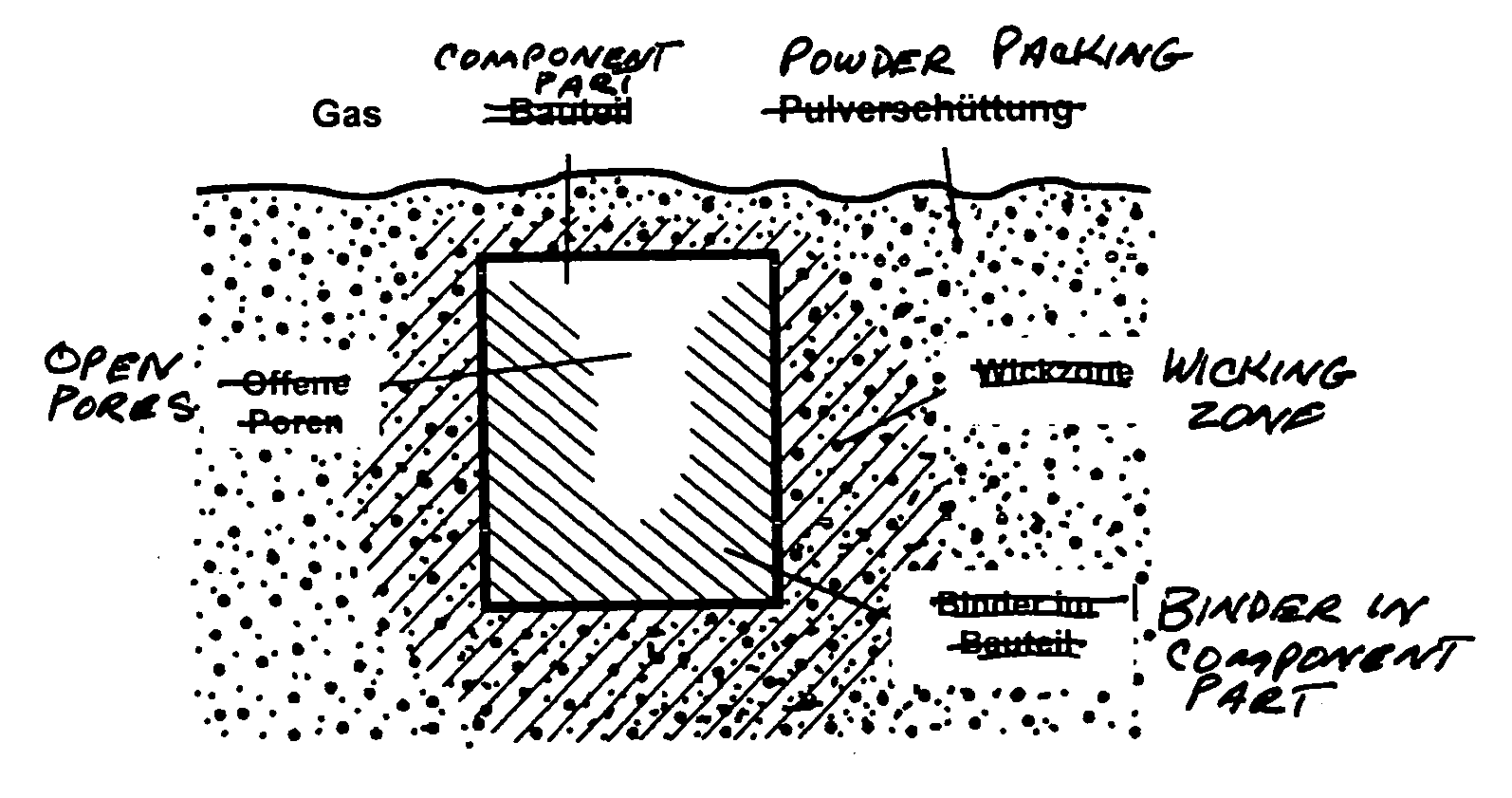
[0043] Wicking Parameter:

[0044] in ZrO.sub.2 sand with a particle size <10 .mu.m with use of filter paper.

[0045] a flowing argon atmosphere or vacuum.

[0046] up to 4 hours at 120.degree.- 150.degree. C.

[0047] Then the samples are removed from the wicking sand.

[0048] Debinding / sintering parameters (sintering support ZrO.sub.2):

[0049] at a rate of 1 K / minute from room temperature to 450.degree. C. under a flowing argon atmosphere,

[0050] holding time at 450.degree. C.: 2 hours,

[0051] heating at a rate of 5 K / minute to 1250.degree. C.,

[0052] holding time 5 hours,

[0053] all under a protective gas (argon, 1270 mbar).

[0054] The sinter density achieved corresponded to 95% of theoretical density.

3TABLE 1 Impurities of carbon, nitrogen and oxygen in the starting material as well as after debinding or sintering of the component parts. C N O % by weight % by weight % by weig...


PUM

PropertyMeasurementUnit
weight %aaaaaaaaaa
weight %aaaaaaaaaa
viscosityaaaaaaaaaa

Abstract

The invention relates to a method for producing component parts with a high degree of dimensional precision, made of NiTi-shape memory alloys. The invention makes it possible to apply a known metal injection moulding method to NiTi-shape memory alloys by adapting the binding system, temperature control and reducing the time necessary for debinding.

Description

[0001] The invention relates to a method of producing component parts, especially a method for producing component parts to near final dimensions with the aid of metal injection molding.STATE OF THE ART[0002] Metal injection molding (MIM=Metal Powder Injection Molding), also called metal powder injection, is known for a method of mass producing metallic component parts, especially for the manufacture of such component parts to near final contours (NNS=near net shape) R. M. German, A Bose (editors): "Injection Molding of Metals and Ceramics", New Jersey, Metal Powder Industries Federation MPIF (1997)).[0003] The MIM process allows small to middle size complex shaped parts to be produced in large numbers in an economical and automated manner. The MIM process supplies component parts with a density of 95 to 98% of the theoretical density and which with subsequent hot isostatic pressing can produce bodies (without encapsulating material) with a density of 100%.[0004] The method encompas...

Claims


Application Information

Patent Timeline
Patent Type & Authority Applications(United States)
IPC IPC(8): B22D17/00B22F1/10B22F1/103B22F3/02B22F3/10B22F3/22C22C1/04
CPCB22F1/0059B22F3/1025B22F3/22B22F3/225B22F2001/0066C22C1/0491B22F2998/00B22F1/103B22F1/10C22C1/047
Inventor NELLES, HEINZBADER, VOLKERBUCHKREMER, HANS-PETERAHMAD-KHANLOU, ARIANE MARJAMBRAM, MARTINSTOVER, DETLEV
Owner FORSCHUNGSZENTRUM JULICH GMBH
Why Eureka
Try Eureka