Injection molding machine and controller

An injection molding machine and controller technology, applied in the field of injection molding machines, can solve the problems of high energy consumption, uncontrolled, wasted energy, etc., and achieve the effects of low energy consumption, low clamping pressure, and fast air discharge

Inactive Publication Date: 2006-01-25
乔斯・R・马拉齐塔
View PDF4 Cites 10 Cited by
  • Summary
  • Abstract
  • Description
  • Claims
  • Application Information

AI Technical Summary

Problems solved by technology

Today, molding machines are capable of high throughput, but molding operations typically face two distinct problems: (1) evacuation of air trapped in the mold cavity where the molding material is injected; and (2) high energy consumption
During the retracting auger rotation phase of the injection cycle, the pressure to the auger is usually not controlled and only the flow to the auger is controlled with a flow control valve, again wasting precious energy

Method used


Image

  • Injection molding machine and controller
  • Injection molding machine and controller
  • Injection molding machine and controller

Examples


Embodiment Construction

[0031] The injection molding process is a combination of art and science. It allows an experienced mold setter to properly run a particular mold on a particular molding machine. These individuals make the best possible part at the lowest possible cost through differential control of the machinery, molds, and other auxiliary equipment involved in the forming process. Thus, the molding machine preferably provides all the controls the setter needs to do his job.

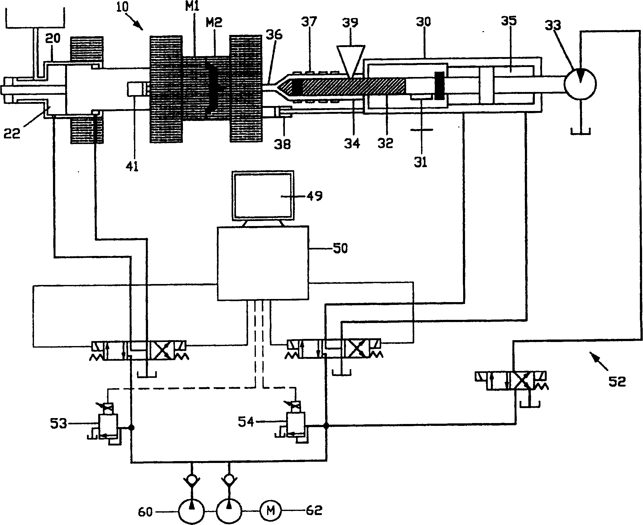
[0032] figure 1 An injection molding machine 10 is schematically shown, which manufactures molded parts by injecting material into a two-part mold shown M1 , M2 , the mold part. The mold can have more than two parts (multi-part mold), but two parts are required. The mold clamping mechanism includes at least one clamping cylinder 20 for applying mold clamping force to the two-part mold and for removing the mold parts to open the mold. An injection mechanism 30 is provided for plasticizing the material and injecting ...


PUM


Abstract

An injection molding machine 10 utilizes a two part mold to produce a molded part. A machine includes a clamping mechanism 20 including one or more clamping cylinders 22 for applying a mold clamping force to the two part mold, an injection mechanism 30 for plasticizing material and injecting the plasticized material into the closed mold, and a controller 50 for powering the molding machine hydraulic system 52. In one embodiment, clamping pressure is automatically increased or decreased to allow air to escape as plasticized material flows into the mold cavity. In another embodiment, the controller provides a minimum clamp pressure to maintain the plasticized material within the mold as a function of fluid injection pressure to the screw member of the injection system.

Description

technical field [0001] The invention relates to an injection molding machine for manufacturing molded parts by injecting plastic material into a two-part mould. More particularly, the present invention relates to an improved injection molding machine controller coupled to a hydraulic system for more efficient operation of the molding machine. Background technique [0002] Injection molding machines, which form parts by injecting material into a two-part mold, have gained widespread use over the past two decades. Injection molding machines transform plastic or rubber materials from one form or shape to another. Most moldable materials start out as spheres, while others come as rods, powders, or meshes. Molding machines typically include a clamping mechanism, including one or more clamping cylinders, for applying mold clamping force to a two-part (or multi-part) mold and for moving the mold parts to open the mold; and for plasticizing the material And the injection mechanis...

Claims


Application Information

Patent Timeline
Patent Type & Authority Applications(China)
IPC IPC(8): B29C45/77B29C45/80B29C45/82B29C45/34B29C45/76
CPCB29C45/7653B29C45/34
Inventor 乔斯·R·马拉齐塔
Owner 乔斯・R・马拉齐塔
Why Eureka
Try Eureka