Image color adjusting method

A color adjustment and color technology, applied in the direction of color signal processing circuits, etc., can solve problems such as color adjustment, and achieve the effect of reducing complexity and cost

Active Publication Date: 2006-12-13
CPT TECH GRP
View PDF2 Cites 6 Cited by
  • Summary
  • Abstract
  • Description
  • Claims
  • Application Information

AI Technical Summary

Problems solved by technology

The second problem is that even if the input source is a digital red, green, blue (abbreviated as RGB) signal, it must first be converted to the above-mentioned Y, R-Y, B-Y mode, and then swi

Method used


Image

  • Image color adjusting method
  • Image color adjusting method
  • Image color adjusting method

Examples


Embodiment Construction

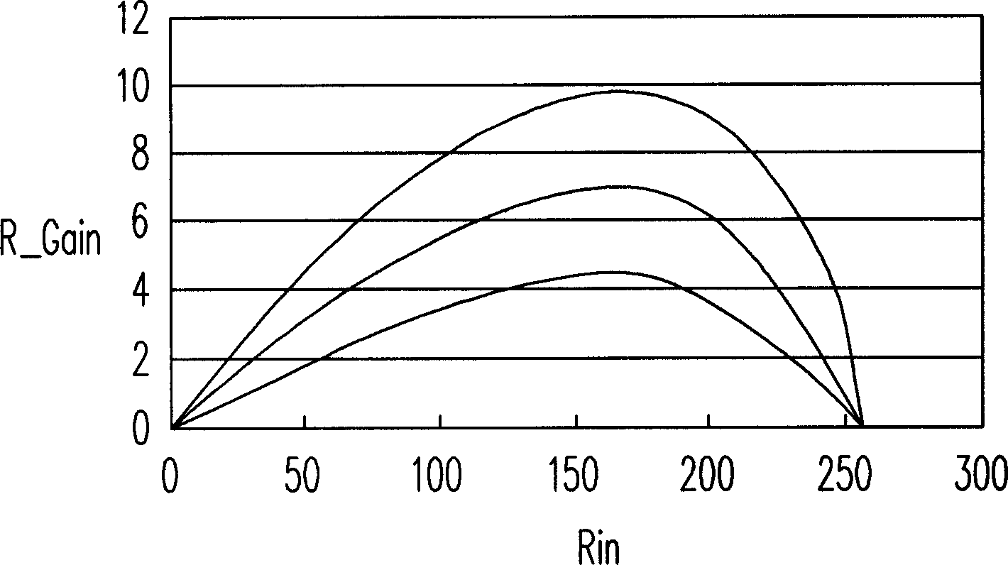
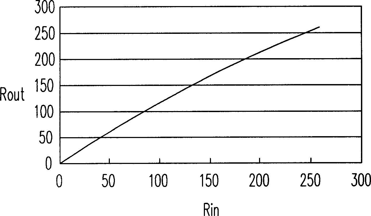
[0038] The following description is an image color adjustment method according to an embodiment of the present invention. In this embodiment, an image is composed of multiple pixels, and each pixel has a corresponding color signal to determine the red, green, and blue gray levels of the pixel. To put it simply, the image color adjustment method of this embodiment first determines whether the color signal of the pixel is within a specific adjustment range. If so, the value of the adjustment factor is determined according to the distance between the color signal and the boundary of the adjustment range. Then adjust the red, green and blue gray levels of the color signal according to the adjustment factor.

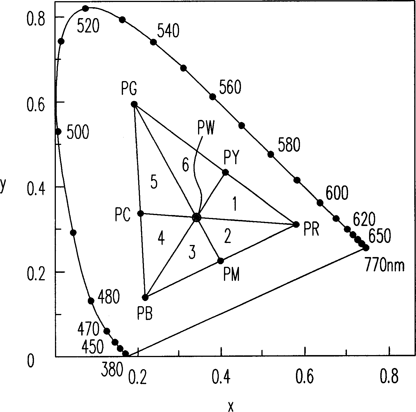
[0039] Therefore, first of all, it is necessary to judge whether the color signal is within the adjustment range. The adjustment range of this embodiment is defined in figure 1 The chromaticity diagram (chromaticity diagram). exist figure 1 Among them, the three primary ...


PUM


Abstract

The invention relates to a method for adjusting the color of image, which can adjust the image color in special range at RGB mode, without color mode conversation, and can gradually change the adjusted edge, to avoid generating error profile. Said method comprises following steps that: judging if the color signal in the adjusting range, if it is, according to the distance between the color signal and the edge of adjusting range, deciding the value of adjust factor; then according to the adjust factor, adjusting the red, green, and blue grays of color signal.

Description

technical field [0001] The invention relates to an image color adjustment method, and in particular to an image color adjustment method for a specific range. Background technique [0002] At present, most of the TV transmission signals are transmitted by Y (brightness) and C (color) separation technology, and the above-mentioned C signal is used to convert the color into R-Y and B-Y to represent the hue (hue) and saturation ( saturation), where R and B are the red and blue signals of the three primary colors, respectively. Therefore, the traditional method is mostly to adjust the hue, saturation and brightness contrast under such a color model. [0003] However, the conventional approach suffers from two problems. The first is that all colors can only be adjusted at the same time, and cannot be adjusted for a specific color area. For example, enhance the saturation of specific color areas such as blue sky and white clouds, green leaves, sunset, etc., to make the image dis...

Claims


Application Information

Patent Timeline
IPC IPC(8): H04N9/68
Inventor 林享昙李育儒
Owner CPT TECH GRP
Why Eureka
Try Eureka