Pressing cylinder, preferably for use in a refuse compressor

A technology of garbage compressor and pressure cylinder, applied in the direction of presses, punching machines, trash cans, etc., can solve the problems of large size and weight, difficult to handle, etc., and achieve the effect of reducing transportation and saving costs.

Inactive Publication Date: 2006-12-13
MIL TEK BALERS
View PDF0 Cites 1 Cited by
  • Summary
  • Abstract
  • Description
  • Claims
  • Application Information

AI Technical Summary

Problems solved by technology

As a result, the size and weight of such cylinders is large and difficult to handle, so it is limited to large recycling centers

Method used


Image

  • Pressing cylinder, preferably for use in a refuse compressor
  • Pressing cylinder, preferably for use in a refuse compressor
  • Pressing cylinder, preferably for use in a refuse compressor

Examples


Embodiment Construction

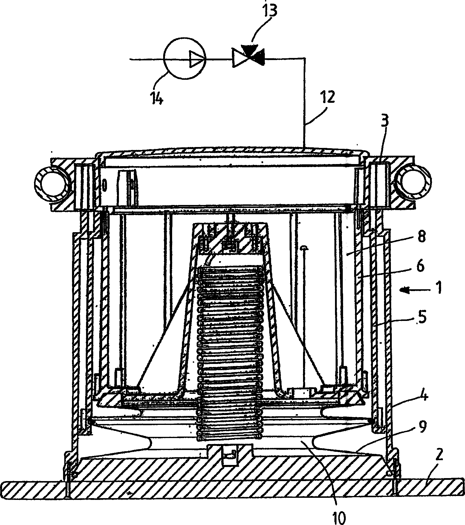
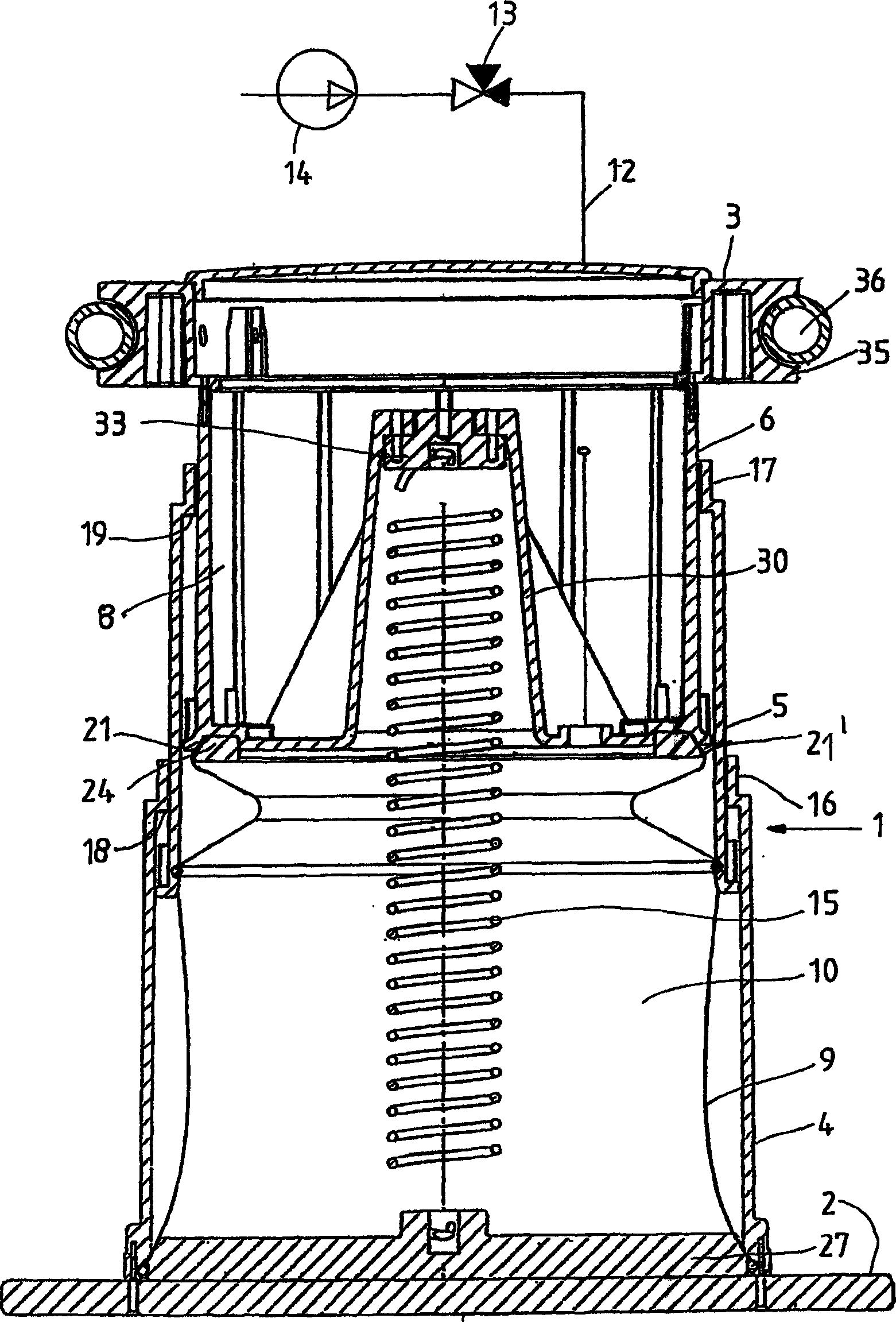
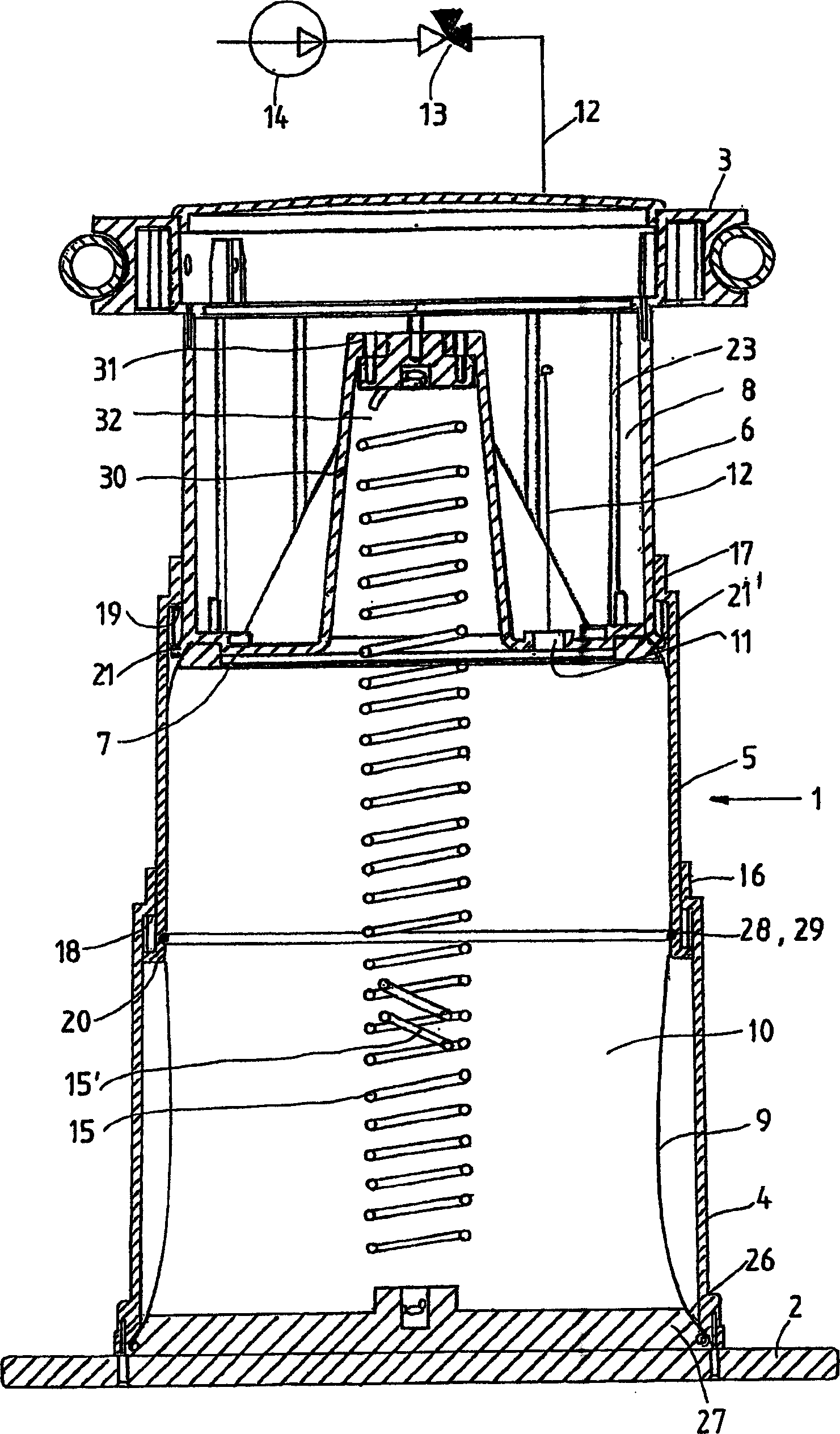
[0018] As shown in the figure, the bottom of the pressure cylinder 1 is connected with the pressing plate 2, and the top is connected with the top plate 3 fixed on the frame. The pressure cylinders are generally oriented vertically and can move the platen in an upward or downward direction.

[0019] As shown in the figure, the pressure cylinder according to the present invention is composed of many cylinder sections, preferably three sections, namely the first and bottom cylinder section 4, the second and middle section 5 and the third and upper section located at the bottom and fixed to the pressure plate 2 The cylinder section 6 and the cylinder section 5 can move telescopically along the longitudinal direction of the cylinder in the first cylinder section, and the cylinder section 6 can move telescopically in the second cylinder section. A bottom plate 7 is formed on the bottom of the third cylinder section 6 , and the bottom plate 7 together with the cylinder barrel of the...


PUM


Abstract

A pressing cylinder (1), preferably for use in a refuse compressor for compression of refuse, which when in use is preferably in a vertical position, and at the bottom is coupled to a pressing plate (2) and at the top to a secured top plate (3) and which can activate the pressing plate in upward and downward directions, is composed of preferably three cylinder sections, namely a first and lower cylinder section (4), which at the bottom is attached to the pressing plate (2), a second and intermediate cylinder section (5), which can be displaced telescopically in the cylinder's longitudinal direction on the first cylinder section (4), and a third and upper cylinder section (6), which at the top is attached to the top plate (3), and which can be displaced telescopically on the second cylinder section (5). The cylinder section (6) is at the bottom embodied with a bottom plate (7), which in combination with the cylinder section (6) and the top plate delimits a closed hollow space (8). Between the periphery of the bottom plate (7) and the bottom edge of the cylinder barrel of the cylinder section (4) there is internally in the pressing cylinder clamped an approximately cylinder-shaped bendable diaphragm in the cylinder's extended position, whereby an airtight space (10) is created internally in the pressing cylinder. The bottom plate (7) is embodied with an access opening for compressed air, which is admitted to the space (10) through a pipe (12) from a three-way valve (13), which in an initial position opens for compressed air from a compressor (14), and in a second position opens the space (10) to the atmosphere.

Description

technical field [0001] The invention relates to a waste compactor of the type described in the preamble of claim 1 . Background technique [0002] Known refuse compactors use a double-acting hydraulic cylinder. Such a pressure cylinder requires a long stroke corresponding to the movement of the pressure plate. Moreover, due to its high working pressure, the thickness of the cylinder wall must be very large. Therefore, the size and weight of such a pressure cylinder is large and difficult to handle, so its use is limited to large recycling centers. Contents of the invention [0003] The object of the present invention is to describe a pressure cylinder which does not have the disadvantages of known pressure cylinders. [0004] This is achieved by implementing a pressure cylinder according to the characterizing part of claim 1 . This will have the effect that the length of the cylinder in the no-load position is substantially smaller than the stroke length of the cylinde...

Claims


Application Information

Patent Timeline
Patent Type & Authority Applications(China)
IPC IPC(8): B30B1/38B30B15/06B30B9/30B65F1/14
CPCB30B9/305B30B1/38B30B9/3042B30B1/36B30B9/3085
Inventor K·斯坎内鲁普
Owner MIL TEK BALERS
Why Eureka
Try Eureka