Eureka AIR delivers breakthrough ideas for toughest innovation challenges, trusted by R&D personnel around the world.

Pipeline sprayer

A technology of pipe spraying and spraying cavity, applied in the direction of coating, spray booth, spraying device, etc., can solve the problems of unstable paint spraying speed, uneven spraying of paint, poor spraying effect, etc. Efficiency, not easy to oxidize and stick, good effect

Active Publication Date: 2018-11-16
浦江县冠宏家居用品有限公司
View PDF5 Cites 12 Cited by
  • Summary
  • Abstract
  • Description
  • Claims
  • Application Information

AI Technical Summary

Problems solved by technology

[0003] At the end of the production process, industrial pipelines often need to be sprayed for anti-corrosion and anti-rust treatment. The existing industrial pipeline painting device has a complex structure and poor painting effect. The paint cannot be evenly sprayed on the surface of the pipeline, and the pressure inside the pipeline changes greatly. , The paint spraying speed is unstable and the amount of material is uneven

Method used


Image

  • Pipeline sprayer
  • Pipeline sprayer
  • Pipeline sprayer

Examples


Embodiment 1

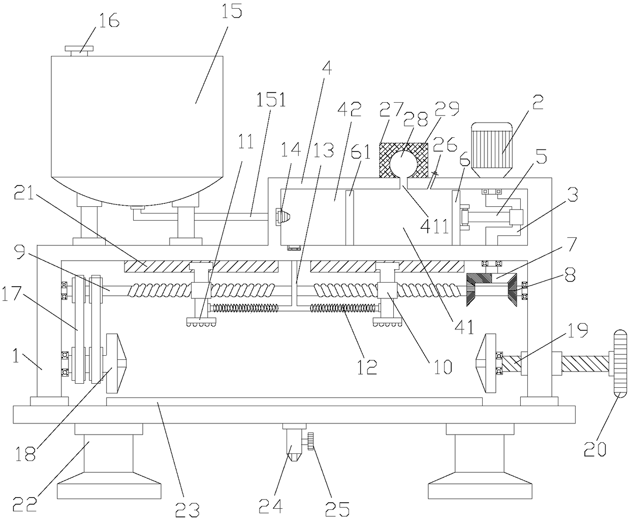
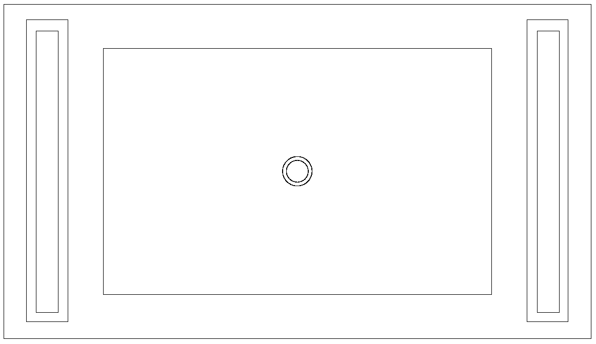
[0034] Such as figure 1 and figure 2 As shown, a pipe sprayer, including Rack 1 , a pressurized material storage mechanism located above the frame 1, a feeding mechanism connected to the output end of the storage mechanism, a driving motor 2 located above the feeding mechanism, a transmission mechanism connected to the output end of the driving motor 2, and A paint spraying mechanism connected to the output of the feeding mechanism.

[0035]The above-mentioned feeding mechanism includes a feeding chamber 4 , a feeding piston 6 arranged in the feeding chamber 4 , and an air pressure balance device matched with the feeding piston 6 . A crankshaft 3 is rotatably connected to the downward output end of the above-mentioned drive motor 2, and a connecting rod 5 is rotatably connected between the feed piston 6 and the crankshaft 3. The operation of the drive motor 2 drives the crankshaft 3 to rotate, and the rotation of the crankshaft 3 further drives The connecting rod 5 and th...

Embodiment 2

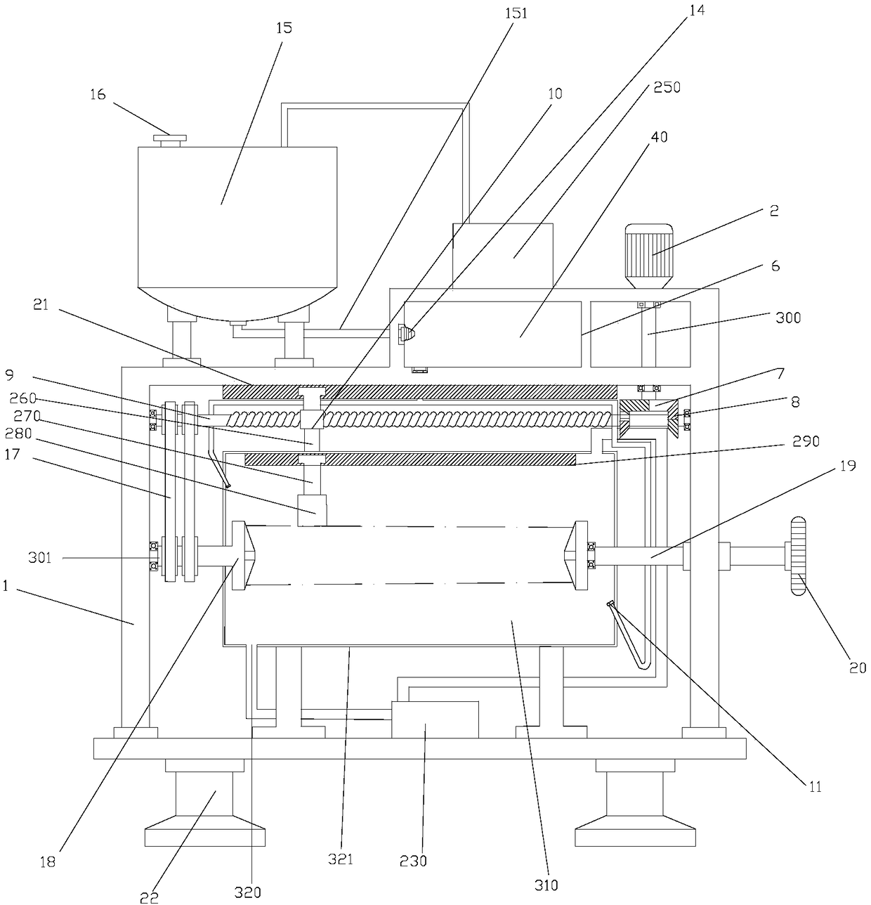
[0042] Such as image 3 and Figure 4 As shown, an industrial pipeline spraying device includes a feeding module, a spraying module and a frame 1 . The upper left side of the above-mentioned frame 1 is fixedly connected to the storage tank 15, the upper end of the storage tank 15 is provided with a feeding port 16 and an air intake hole, the upper right side of the frame 1 is fixedly connected to the air pump 250, and the feeding cavity 4 is arranged below the air pump, and the storage tank 15 lower ends communicate with the feeding pipe. The output end of the air pump 250 is connected to the material storage tank 15, and the material storage tank 15 feeds the material feeding chamber 4 one-way through the material delivery pipe 151 and the one-way valve 14 in sequence. The upper part of the feeding cavity 4 is fixedly connected to the driving motor 2, the lower end of the driving motor 2 is connected to the upper end of the shaft 300, and the lower end of the shaft 300 is f...


PUM


Abstract

The invention discloses a pipeline sprayer. The pipeline sprayer comprises a rack, a storage mechanism arranged above the rack and having a pressurization function, a feeding mechanism connected withan output end of the storage mechanism, a drive motor arranged above the feeding mechanism, a transmission mechanism connected with an output end of the drive motor and a paint spraying mechanism connected with an output end of the feeding mechanism, wherein the feeding mechanism comprises a feeding cavity body, a feeding piston arranged in the feeding cavity body and an air-pressure balance device matched with the feeding piston; a crank is rotationally connected to the downward output end of the drive motor; a connection rod is rotationally connected between the feeding piston and the crank;under the co-action of the elasticity of air-pressure balance balls and the elasticity of fluffy fillers, an air pressure in an air cavity and a pressure given to a spray cavity by a pressurizer aremutually balanced, and then stable conveying for a paint is ensured; and moreover, due to the wrapping of the fluffy fillers, the occurrence of the case that the pressure balance balls are broken dueto a too high pressure, is avoided.

Description

technical field [0001] The invention relates to a pipeline treatment device, in particular to a pipeline sprayer. Background technique [0002] Industrial pipelines are process pipelines, public engineering pipelines and other auxiliary pipelines required by industrial and mining enterprises and institutions for the production and production of various products. Industrial pipelines are widely used in various industrial and mining enterprises, public institutions and other industries, and are distributed in various regions of urban and rural areas. Industrial pipelines are the pressure pipelines with the most types of technological processes, the most complex changes in the production and production environment, and the variety of transported media and harsh conditions. [0003] At the end of the production process, industrial pipelines often need to be sprayed for anti-corrosion and anti-rust treatment. The existing industrial pipeline painting device has a complex structu...

Claims


Application Information

Patent Timeline
Patent Type & Authority Applications(China)
IPC IPC(8): B05B16/00B05B13/02B05B16/20B05C1/06
CPCB05B9/047B05B13/0228B05B13/0442B05B14/00
Inventor 朱成林蔡毓旻
Owner 浦江县冠宏家居用品有限公司
Why Eureka
Eureka Blog
Learn More