Covert security coating

一种隐形、体层的技术,应用在全息图或光栅,衍射表面的制造,隐形光学装置的制造领域

Inactive Publication Date: 2006-12-20
JDS UNIPHASE CORP
View PDF7 Cites 16 Cited by
  • Summary
  • Abstract
  • Description
  • Claims
  • Application Information

AI Technical Summary

Problems solved by technology

[0019] [17] Contrary to Holmes et al., the prior art U.S. Patent No. 6,987,590 provides a different novel Chromagram TM , where no separation layer is required, but where there are separate color shifting and holographic effects

Method used


Image

  • Covert security coating
  • Covert security coating
  • Covert security coating

Examples


Embodiment Construction

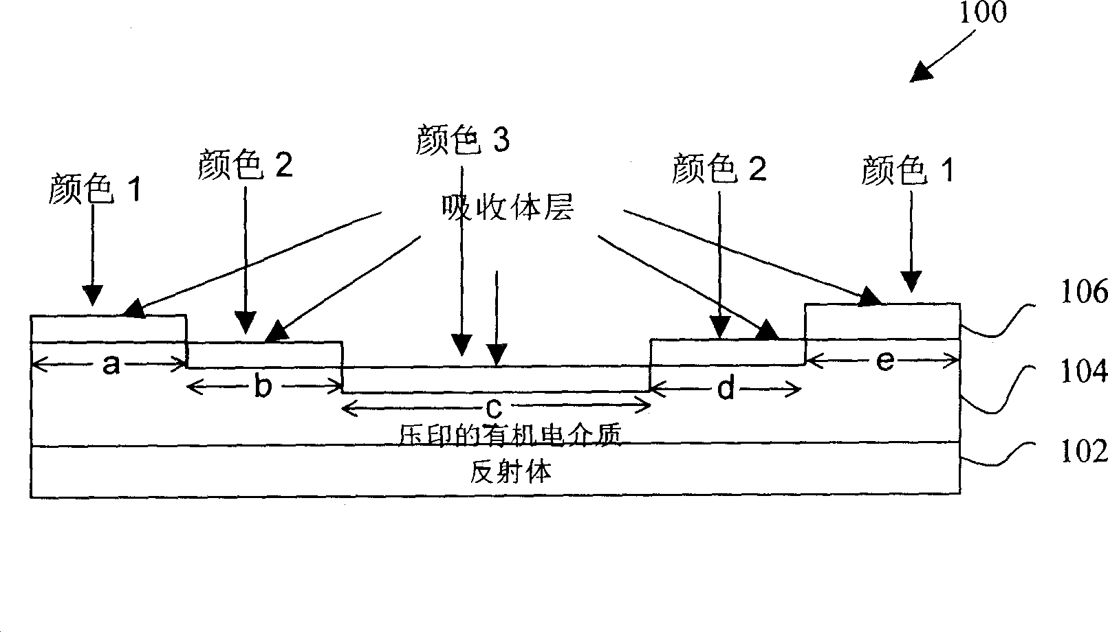
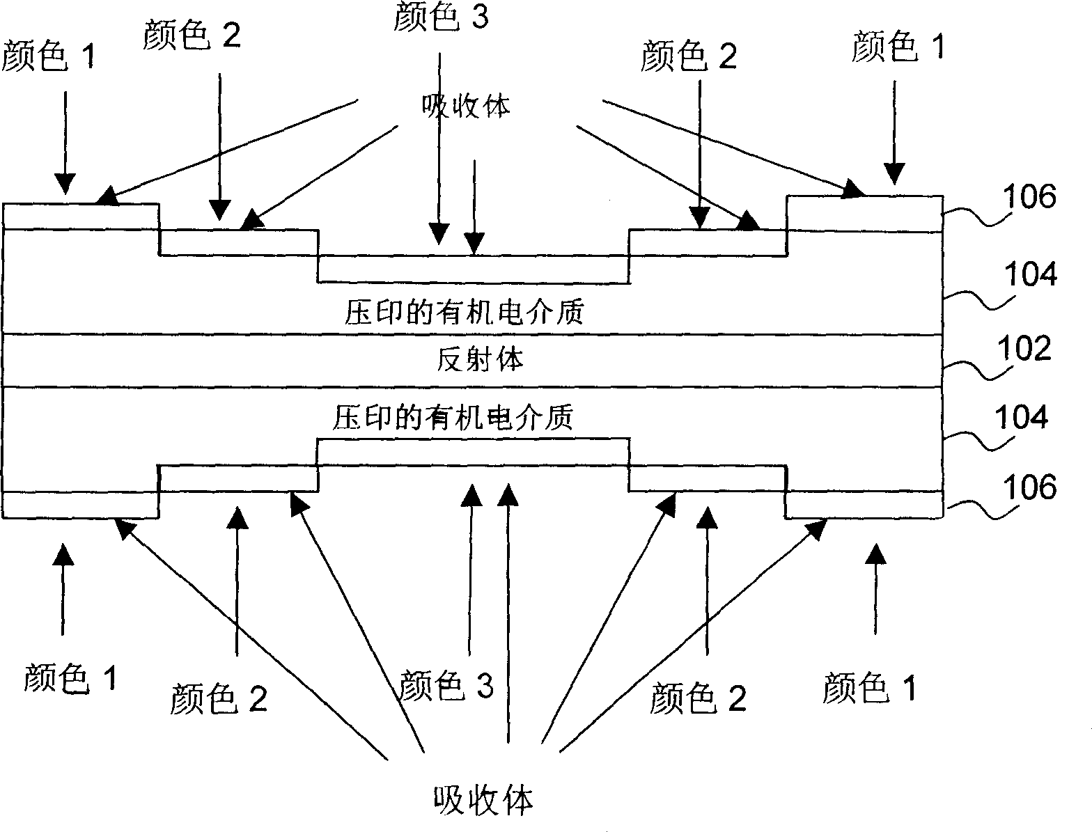
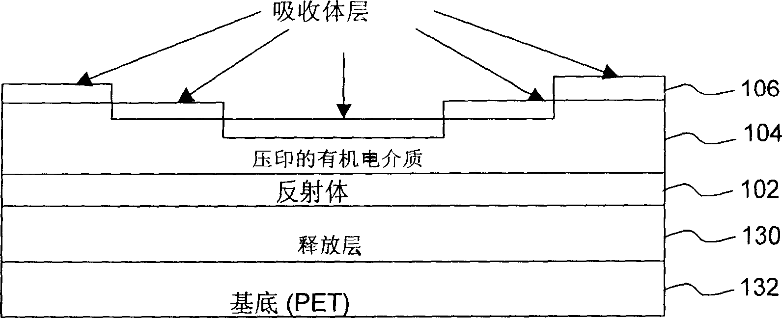
[0075] [58] Now back to figure 1 , a section of a foil 100 is shown in the figure, wherein the foil 100 includes a bottom reflective layer 102 with a uniform thickness; an organic dielectric layer 104 is deposited on the reflective layer 102, and the organic dielectric layer 104 is embossed to have a varying thickness and create dielectric separation regions of varying thickness. An absorber layer 106 of uniform thickness is deposited on the variable thickness organic dielectric layer 104 . In a preferred embodiment, the size of (a) to (e) adjacent regions should be smaller than the size of a pixel or cell that can be seen by human eyes. However, the present invention does not require that all adjacent steps or regions of different thickness be smaller than the size visible to the human eye, but at least one such element or region must have the desired characteristic of being invisible. For example, the size of any unit in (a) to (e) may be small enough to require magnifica...


PUM


Abstract

A multilayer thin film filter is disclosed an organic dielectric layer serving as a spacer layer in a Fabry-Perot structure. The dielectric has embossed regions of varying thicknesses wherein the thickness within a region is substantially uniform. Each different region of a different thickness produces a different color (shift). The size of one of the embossed adjacent regions is such that the color of said one region is uniform and cannot be seen by a human eye as different in color from the uniform color of an adjacent region thereto, and wherein the color within a region can be seen with magnification of at least 10:1. This serves as a covert color coding system useful as a security device.

Description

[0001] Cross References to Related Applications [0002] [01] This application claims priority to US Patent Application No. 60 / 691,499, filed June 17, 2005, which is incorporated herein by reference. technical field [0003] [02] The present invention generally relates to thin-film optical coatings for the manufacture of security articles, and also to the manufacture of diffractive surfaces which can be used as security articles in various applications, for example with color shifting or optically variable Hologram or grating for the background. In particular, the invention relates to the field of coating and / or embossing dielectric substrates to provide gratings or holograms, preferably in a vacuum roll coating chamber, while producing Chromagrams in vacuum TM type device or build a basic device on it to make a Chromagram TM type device. The invention also relates to the fabrication of invisible optical devices having dielectric layers of variable thickness. For example, ...

Claims


Application Information

Patent Timeline
Patent Type & Authority Applications(China)
IPC IPC(8): G02B5/20G02B5/28
CPCG02B5/284G03H1/028G03H2001/188G03H1/0256G03H2270/24G03H1/0244B41M3/003G03H1/0011G03H2225/31B42D2035/24G03H1/0236B42D25/328B41M3/14G03H1/02G02B5/287H01P1/20G03H1/04B42D25/425
Inventor 罗杰·W.·菲利普罗伊·宾
Owner JDS UNIPHASE CORP
Why Eureka
Try Eureka