Multi part non metal implant

A technology of implants and non-metallic materials, applied in the field of implants, can solve problems such as high production costs and high costs, and achieve good adaptability

Inactive Publication Date: 2007-01-03
FRIADENT
View PDF16 Cites 20 Cited by
  • Summary
  • Abstract
  • Description
  • Claims
  • Application Information

AI Technical Summary

Problems solved by technology

However, the method requires high cost to prepare the molding tool and also requires relatively high production cost due to the many process steps required

Method used


Image

  • Multi part non metal implant
  • Multi part non metal implant
  • Multi part non metal implant

Examples


Embodiment Construction

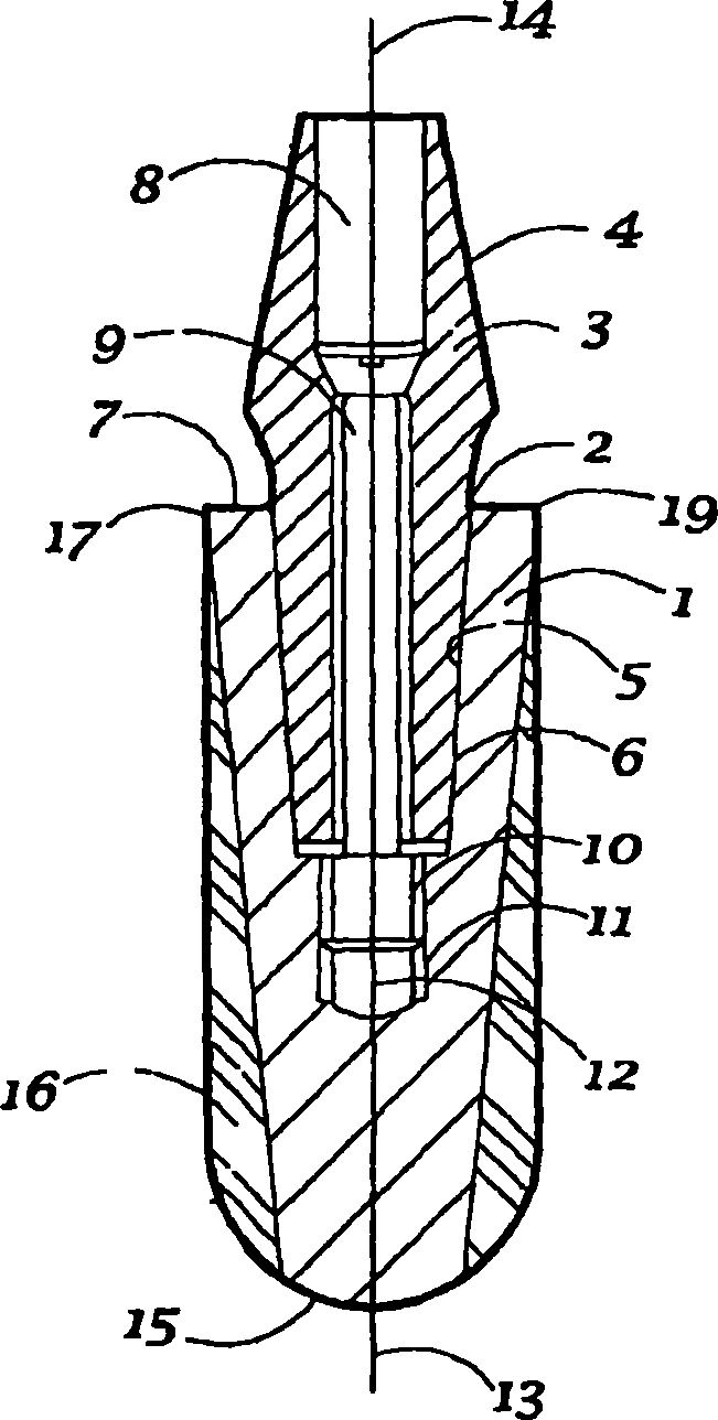
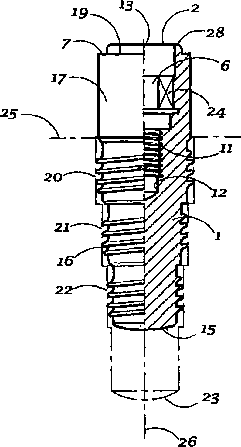
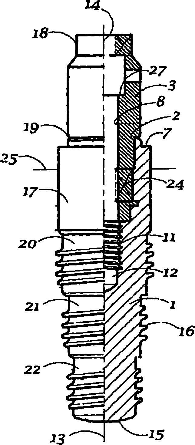
[0037] Figures 1 to 4 Various embodiments of dental implants are shown as examples of the invention. Features common to each embodiment have not been described in detail, although each embodiment has its own advantages in use. Accordingly, similar features in different embodiments will be denoted by the same reference numerals. All descriptions of these embodiments have been presented for purposes of illustration and are exemplary only in nature. Non-described parts or non-description at this point should be construed as limitations of the claims.

[0038] exist figure 1 , shows a two-stage, two-part dental implant which can be positioned steplessly in its direction of rotation, which comprises a first implant fixation part 1 having a central cavity opening 2. The fixing part 1 can be inserted into the jawbone, and the dental implant also includes a second implant abutment part 3, which can support a dental prosthesis superstructure (not shown) like a crown or a bridge. ...


PUM


Abstract

An implant is disclosed comprising a fixture component (1) intended for insertion into a bone, and at least one further abutment component (3) for providing a base for a prosthetic superstructure, and a connecting element (9) for mechanically securing the abutment (3) to the fixture (1), wherein the fixture (1) comprises an external thread (16) or other protrusions for improving engagement between the fixture (1) and the bone, wherein the connecting element (9) detachably interconnects the fixture (1) and the abutment (3), and wherein at least the fixture (1) and the abutment (3) are made of non-metal material, and method of making the same.

Description

technical field [0001] The invention relates to an implant comprising a first fixation part for insertion into a bone, and at least one abutment part providing a base for a superstructure. Background technique [0002] Dental superstructures may include single tooth replacements or dental prostheses. For intraosseous dental implants, a distinction is made between so-called single-stage and two-stage systems. Typically, single-stage implants are performed in a single surgical step and are often used for early filling. Dual-stage implants require two surgical steps. The first step is to insert the implant component into the bone. This step allows for a defined time Healing, ie mainly tissue covering, the second step is, where possible, opening the tissue again, securing another implant component which serves to accomplish the desired functional properties of the implant. For each patient, the best choice is made according to the needs and corresponding medical concepts. In ...

Claims


Application Information

Patent Timeline
Patent Type & Authority Applications(China)
IPC IPC(8): A61C8/00A61C13/00
CPCA61C8/0006A61C8/0045A61C8/0012A61C2008/0046A61C8/0071A61C8/0069A61C8/0054A61C8/006A61C8/005A61C8/0068A61C8/0013A61C8/0022A61C13/0003A61C8/00
Inventor W·迪特里希
Owner FRIADENT
Why Eureka
Try Eureka