Air processing method and device therefor

An air treatment device, the technology of the treatment device, applied in the direction of space heating and ventilation, heating method, air conditioning system, etc.

Inactive Publication Date: 2007-01-10
玛丽亚·赫曼纳斯·吉哈德斯·斯德赫斯
View PDF1 Cites 19 Cited by
  • Summary
  • Abstract
  • Description
  • Claims
  • Application Information

AI Technical Summary

Problems solved by technology

[0005] Furthermore, known air treatment devices are only su...

Method used


Image

  • Air processing method and device therefor
  • Air processing method and device therefor
  • Air processing method and device therefor

Examples


specific Embodiment approach

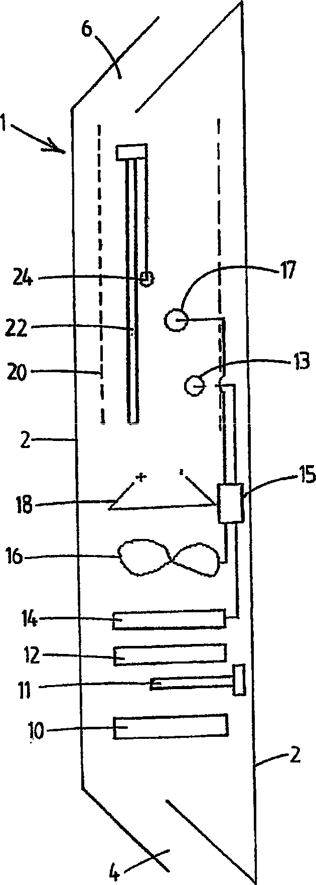
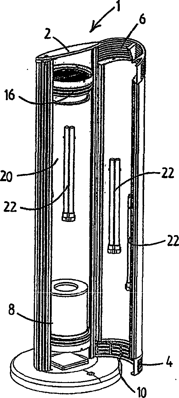
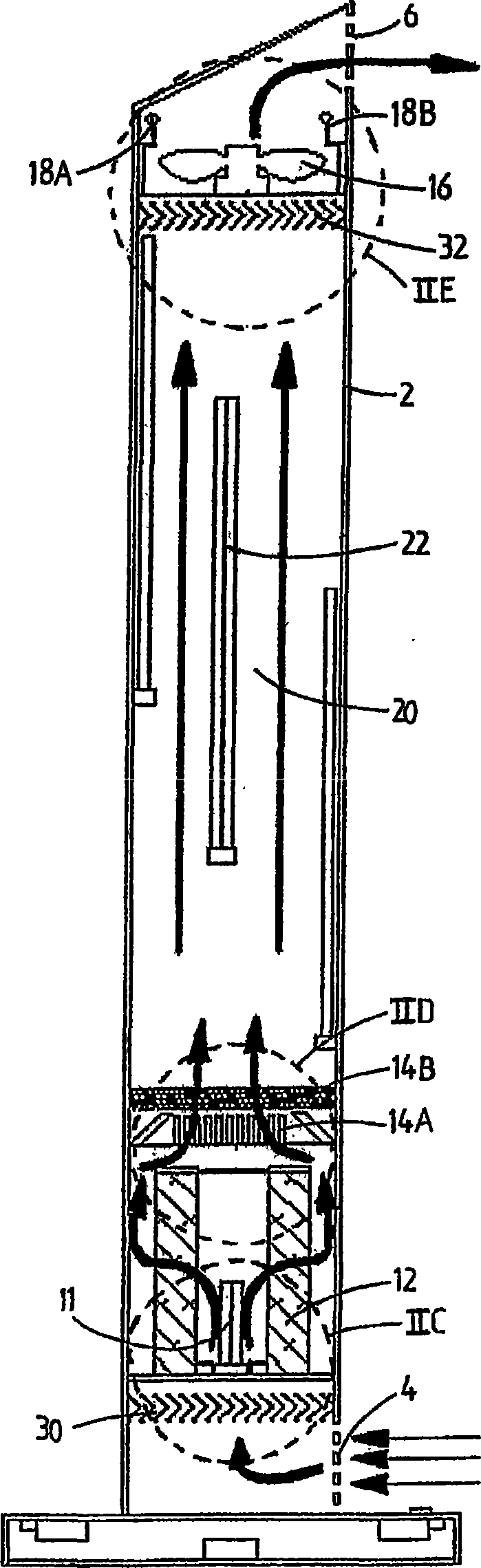
[0053] figure 1 The distribution of the various components in the air handling device generally indicated by reference numeral 1 is schematically illustrated.

[0054] The air handling device 1 comprises an elongated tubular housing 2 having a cross-section generally circular or oval in shape, or any other suitable cross-sectional shape such as a rectangular or polygonal shape. The cross-sectional shape or area of ​​housing 2 may vary along its length. In a preferred embodiment, the cross-section is circular with a constant length along the length of the housing 2 and has a diameter of about 0.2 to 0.3 meters.

[0055] The housing has an air inlet 4 at its first end and an air outlet 6 at its second end. It is generally desired that air flow through the housing 2 from the air inlet 4 to the air outlet 6 . In one embodiment, the longitudinal axis of the housing 2 may be oriented vertically or generally vertically to have an air inlet 4 at the lower end of the housing 2 and a...


PUM


Abstract

In order to improve the air quality in bounded spaces such as a room, an air treatment device and an air treatment method are disclosed. The air treatment device comprises a fan (16) for stimulating airflow through the air treatment device and an UV treatment chamber (20). An UV radiation source (11) radiates UV radiation in the UV treatment chamber to kill microorganisms in said airflow. The air treatment device is designed such that a high airflow may be generated, while all microorganisms present in the air flowing through the air treatment device are killed. With the high airflow and air cleaning capacity, the air treatment device may clean a bounded space in a short period of time.

Description

technical field [0001] The present invention relates to an air treatment method and air treatment device for killing microorganisms present in the air. Background technique [0002] In confined spaces such as rooms, houses, buildings or other human or animal habitation environments, there are countless pollutants such as dust and microorganisms like viruses, bacteria and fungi. These pollutants threaten the health of humans or animals living in these confined spaces. [0003] Air treatment devices for improving the air quality in confined spaces are known (for example from US 5185015). Known air handling units comprise three filters. A first filter filters particles larger than a predetermined size from the air, a second filter filters particles with selected chemicals and a third filter eliminates the ability of airborne bacteria to multiply by emitting ultraviolet light. [0004] However, known air handling devices have a limited air cleaning capacity and have a limited...

Claims


Application Information

Patent Timeline
IPC IPC(8): A61L9/20A61L9/16F24F3/16A61L9/22
CPCY02A50/2351
Inventor 玛丽亚·赫曼纳斯·吉哈德斯·斯德赫斯
Owner 玛丽亚·赫曼纳斯·吉哈德斯·斯德赫斯
Why Eureka
Try Eureka