Systems and methods for bypassing an inlet air treatment filter

a technology of inlet air treatment and filter system, which is applied in the direction of auxillary pretreatment, separation process, filtration separation, etc., can solve the problems of reducing the operating efficiency of gas turbine engines, reducing the air flow to compressors, and 0.5′′ water column pressure drop

Active Publication Date: 2011-04-14
PARKER INTANGIBLES LLC
View PDF18 Cites 54 Cited by
  • Summary
  • Abstract
  • Description
  • Claims
  • Application Information

AI Technical Summary

Problems solved by technology

However, at least some known pre-filters cause a pressure drop of about 0.5″ of water column under normal operating conditions.
Over time, the pressure drop across the pre-filters and filter may increase which may resul

Method used


Image

  • Systems and methods for bypassing an inlet air treatment filter
  • Systems and methods for bypassing an inlet air treatment filter
  • Systems and methods for bypassing an inlet air treatment filter

Examples


Embodiment Construction

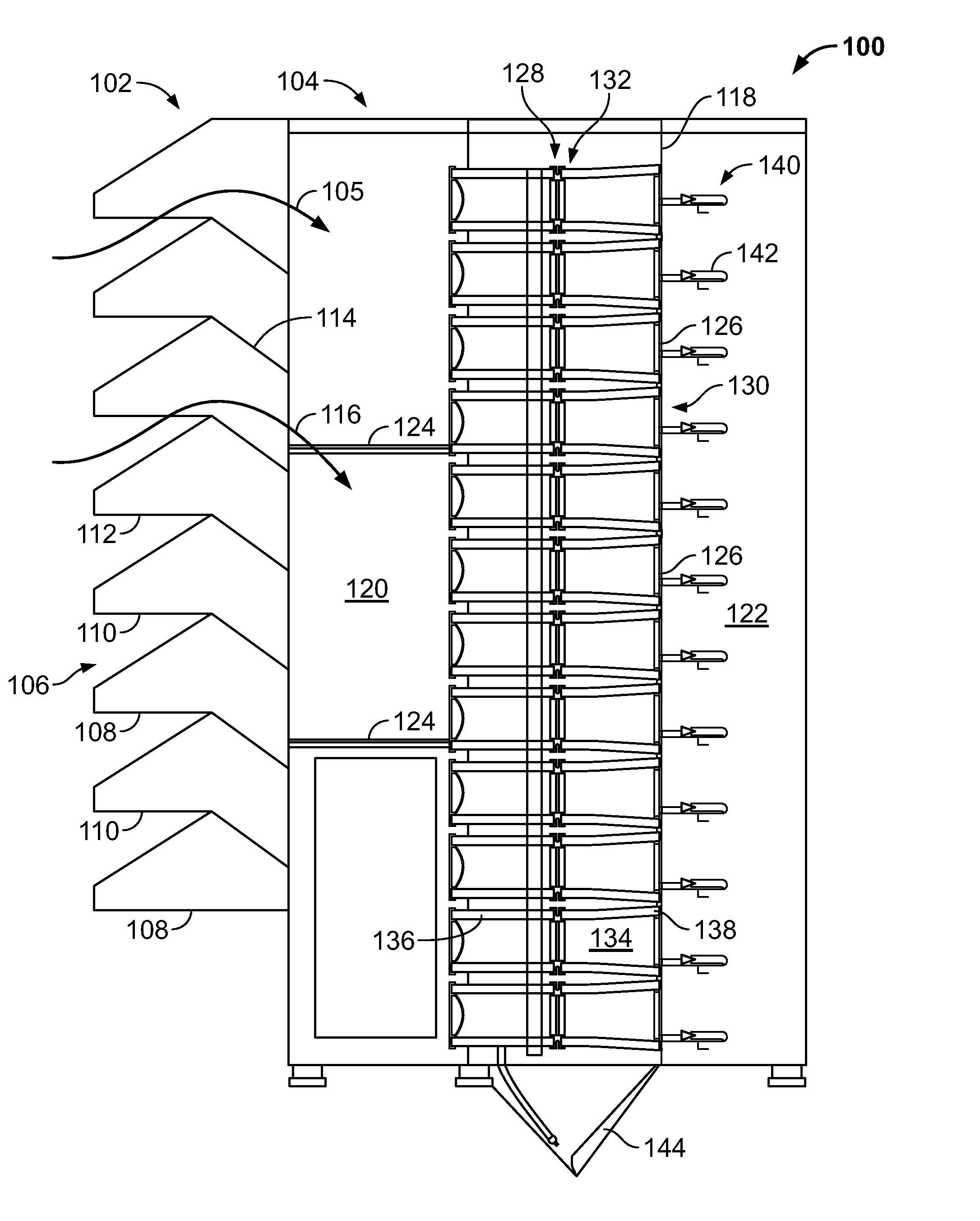
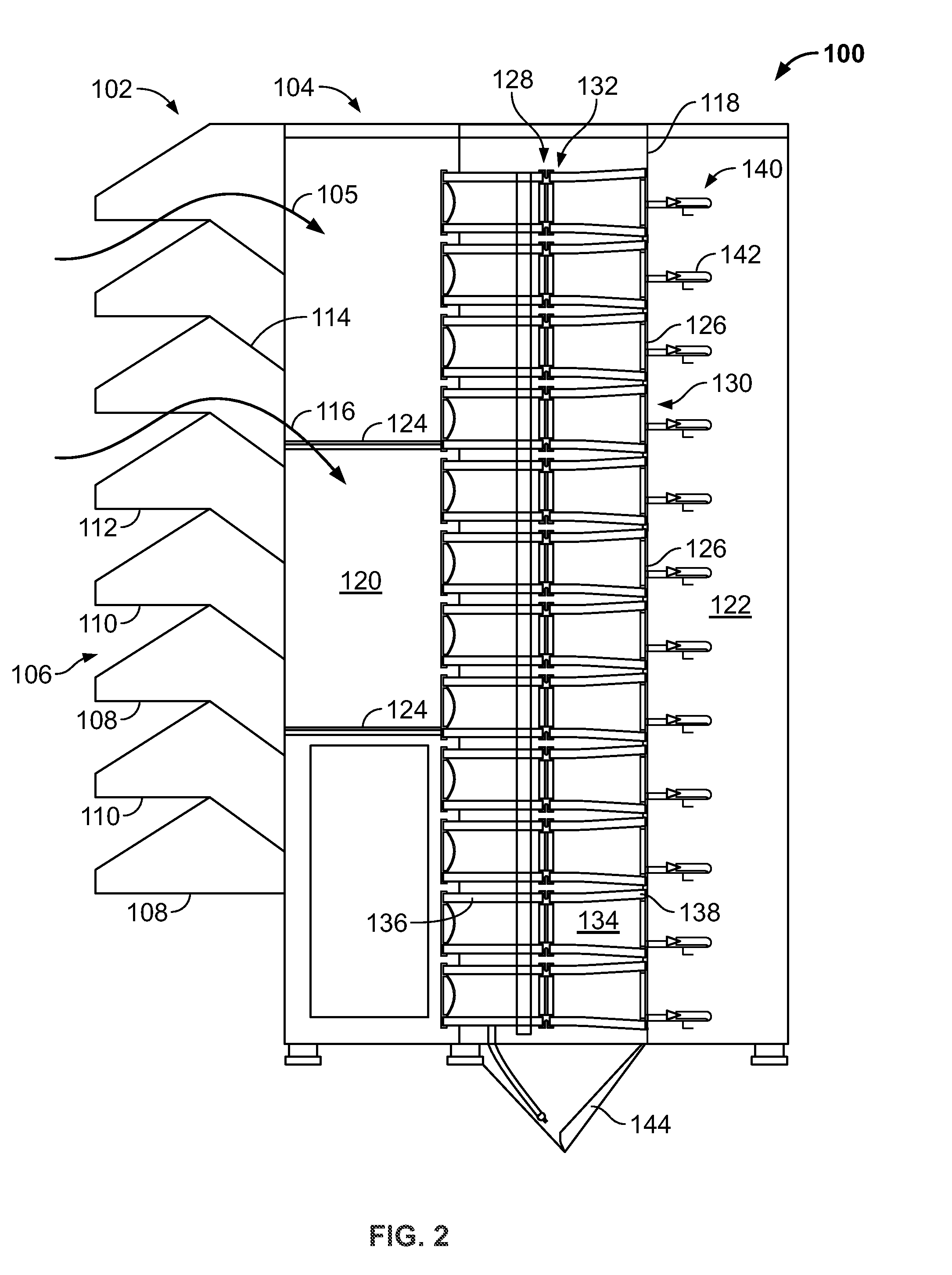
[0013]The exemplary methods and systems described herein overcome the disadvantages of known inlet air treatment systems by providing a pre-filter bypass assembly that enables an inlet air pre-filter to be removed from operation without requiring a shutdown of the associated turbine engine. More specifically, the embodiments described herein facilitate bypassing a pre-filter during operating periods when the pressure drop through the inlet air treatment system is high enough to reduce compressor operating efficiency and / or to result in a compressor surge that may damage the compressor. In addition, the embodiments described herein facilitate automatically bypassing the intake air pre-filter without requiring a human operator to remove the pre-filter from service.

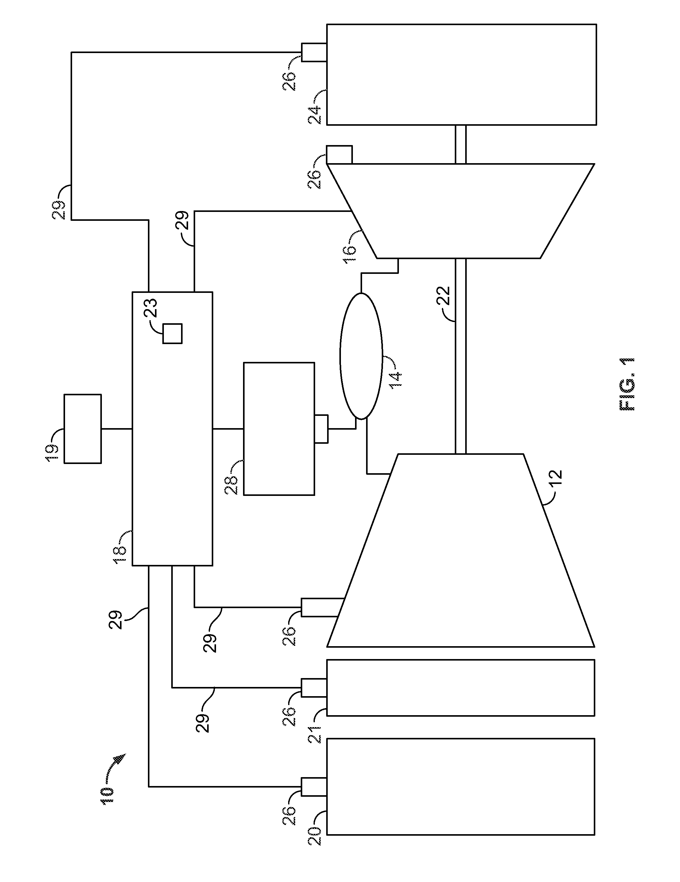
[0014]FIG. 1 is a schematic diagram of a gas turbine engine system 10. In the exemplary embodiment, gas turbine engine system 10 includes an inlet air treatment system 20, a compressor 12, a combustor 14, a turbine 16 rotata...


PUM

PropertyMeasurementUnit
Temperatureaaaaaaaaaa
Pressure dropaaaaaaaaaa

Abstract

A method of assembling an inlet air filter assembly for use with a turbine engine system. The method includes coupling an inlet hood to an air filter enclosure, such that an airflow path is defined between the inlet hood and the air filter enclosure. A pre-filter is coupled to the inlet hood, such that the pre-filter is positioned within the airflow path. A filter bypass assembly is coupled to the pre-filter for moving the pre-filter from an operating position to a bypass position during operation of the turbine engine system.

Description

BACKGROUND OF THE INVENTION[0001]The present invention relates generally to inlet air treatment systems, and more specifically to systems and methods for bypassing inlet air pre-filter systems for gas turbine engines.[0002]At least some gas turbine engines include a compressor section, a combustor section, and at least one turbine section. The compressor compresses air, which is mixed with fuel and channeled to the combustor. The compressor compresses air, that is mixed with fuel and channeled to the combustor. The mixture is then ignited generating hot combustion gases that are then channeled to the turbine. The turbine extracts energy from the combustion gases for powering the compressor, as well as producing useful work to power a load, such as an electrical generator, or to propel an aircraft in flight.[0003]At least some known gas turbine engine systems include inlet air treatment systems that remove moisture and / or dust from air channeled to the compressor. At least some known...

Claims


Application Information

Patent Timeline
IPC IPC(8): F02K3/04B01D50/00B01D46/46B01D53/04B01D46/44B23P17/00
CPCB01D46/42Y10T29/49229B01D2273/14B01D29/96B01D46/44B01D46/46B01D50/00F02C7/055
Inventor UPADHYAY, SIDDHARTHCHILLAR, RAHUL J.
Owner PARKER INTANGIBLES LLC
Why Eureka
Try Eureka