Heat exchanger and method for manufacturing the same

A technology of heat exchanger and thermal spraying, applied in the direction of heat exchanger fixation, heat exchange equipment, manufacturing tools, etc., can solve problems such as damage to brazing quality, achieve high-quality brazing, and achieve the effect of brazing

Inactive Publication Date: 2007-01-31
SHOWA DENKO KK
View PDF2 Cites 16 Cited by
  • Summary
  • Abstract
  • Description
  • Claims
  • Application Information

AI Technical Summary

Problems solved by technology

Therefore, when the brazing operation is performed by heating the assembled parts, the acrylic series resin cannot be completely evaporated and remains on the tube surface, impairing the brazing quality

Method used


Image

  • Heat exchanger and method for manufacturing the same
  • Heat exchanger and method for manufacturing the same

Examples


example 1

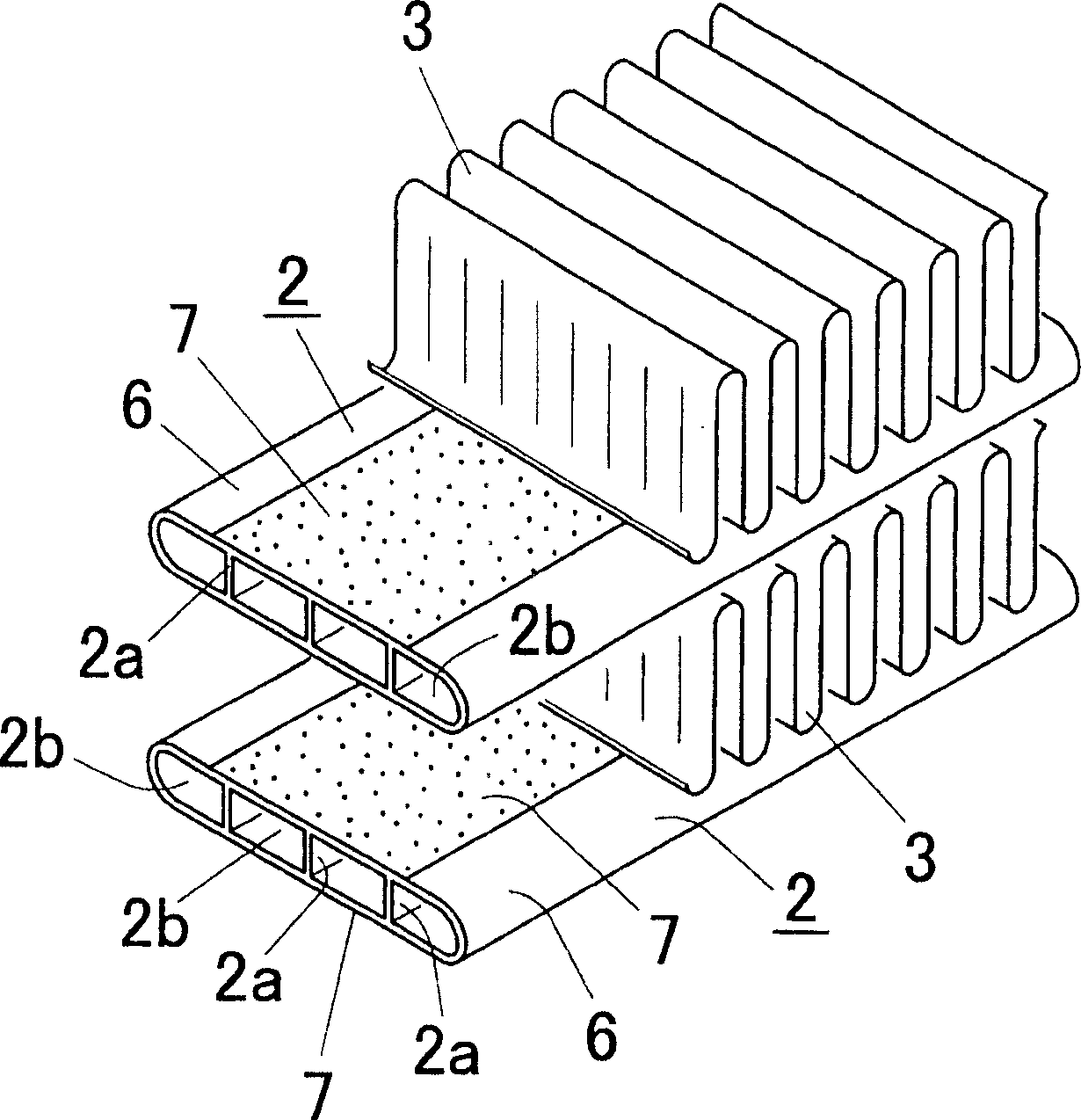
[0094] For the aluminum flat tube that is continuously extruded from the extruder, the brazing material of the Al-Si series alloy (Si content is 6 mass %, and the remainder is Al) is set at a certain position immediately after its extrusion. The pipe is thermally sprayed onto its upper and lower flat surfaces in a thermal spray gun (arc sprayer) above and below the pipe. By using an aluminum alloy (0.4% by mass of Cu, 0.2% by mass of Mn, and the remainder of Al) at a temperature of 450°C, the extruded flat tube is extruded into a width of 16 mm and a thickness (height) A flat tube with a thickness of 3 mm, a wall thickness of 0.5 mm and four hollow parts.

[0095] On the surface of the flat tube 2, KZnF is coated 3 / paraffin = 50 / 50 (mass ratio) flux mixture (KZnF 3 powder dispersed in paraffin). At this point, the flux mixture is applied such that the KZnF 3 The amount of spraying is 10g / m 2 .

[0096] Paraffin (molecular weight: 300) was used as paraffin. The paraffin...


PUM


Abstract

A method for manufacturing a heat exchanger according to the present invention includes the steps of forming a thermally sprayed layer on a surface of an aluminum tube core by thermally spraying Al-Si series alloy brazing material onto the surface of the aluminum tube core to obtain a tube 2, applying flux composite containing non-corrosive flux showing zinc substitution reaction onto a surface of the tube 2, combining the tube 2 with the fin 3, and brazing the tube 2 and the fin 3 in an combined state.

Description

[0001] This application claims the benefit of Japanese Patent Application No. 2003-426408, filed December 24, 2003, and U.S. Provisional Application No. 60 / 532,906, filed December 30, 2003, the entire disclosures of which are taken as a whole It is incorporated herein by reference. [0002] Cross References to Related Applications [0003] This application is an application filed under 35 U.S.C. §111(a) and requested under 35 U.S.C. §119(e)(1) of Provisional Application No. 60 filed December 30, 2003 under 35 U.S.C. §111(b) / 532,906 Filing Date Benefits. technical field [0004] The invention relates to a heat exchanger with excellent corrosion resistance and a manufacturing method thereof. [0005] In this disclosure, the meaning of the term "aluminum" includes aluminum and its alloys. In the present disclosure, "Al" means aluminum (metal elemental substance). Background technique [0006] The following descriptions illustrate the inventor's understanding of the relevan...

Claims


Application Information

Patent Timeline
Patent Type & Authority Applications(China)
IPC IPC(8): B23K1/00F28D1/053F28F1/12
CPCF28F19/02B23K1/0012F28D1/05391B23K2201/14F28F2275/04F28F1/126B23K2101/14Y10T29/49393
Inventor 南和彦山井智明
Owner SHOWA DENKO KK
Why Eureka
Try Eureka