Resilient plate type stereo compact spinning device for spinning machine

A spinning frame and disc-type technology, applied in spinning machines, textiles, papermaking, drafting equipment, etc., can solve problems such as broken yarn, high production cost, complex structure, etc., to avoid yarn blocking and broken yarn, improve Conveying form and the effect of improving yarn quality

Inactive Publication Date: 2007-02-07
绍兴华裕纺机有限公司
View PDF1 Cites 25 Cited by
  • Summary
  • Abstract
  • Description
  • Claims
  • Application Information

AI Technical Summary

Problems solved by technology

For example, a compact spinning device with patent No. 03228410.1 is provided with an air suction pipe with two ends fixed on two adjacent roller seats with air suction port and exhaust port, which is set outside the air suction pipe and corresponds to the position of the air suction port. The cohesive sleeve with a condensation groove in the circumferential direction of the cohesive sleeve, the tension device stuck in the cohesive sleeve, the air-permeable conveying ring and the transmission pressure device set on the cohesive sleeve, the compact spinning device can make the fiber bundle output by the front roller Under the action of negative pressure generated by the exhaust system, it is adsorbed on the air-permeable conveying ring, and under the action of the pressurized transmission device and the air-permeable conveying ring, the fiber bundle is tightened and straightened to achieve twisting into yarn. The yarn device can better solve the original "hairiness" problem and improve the yarn quality, but there are also some shortcomings, such as complex structure and high production cost; and the compact spinning device and the roller are driven by different power devices. It is easy to cause the speed of the compact spinning device to be out of sync with the speed of the rollers, resulting in yarn blocking and yarn breakage
The twisting triangle cannot be eliminated and the yarn quality will be affected

Method used


Image

  • Resilient plate type stereo compact spinning device for spinning machine
  • Resilient plate type stereo compact spinning device for spinning machine

Examples


Embodiment Construction

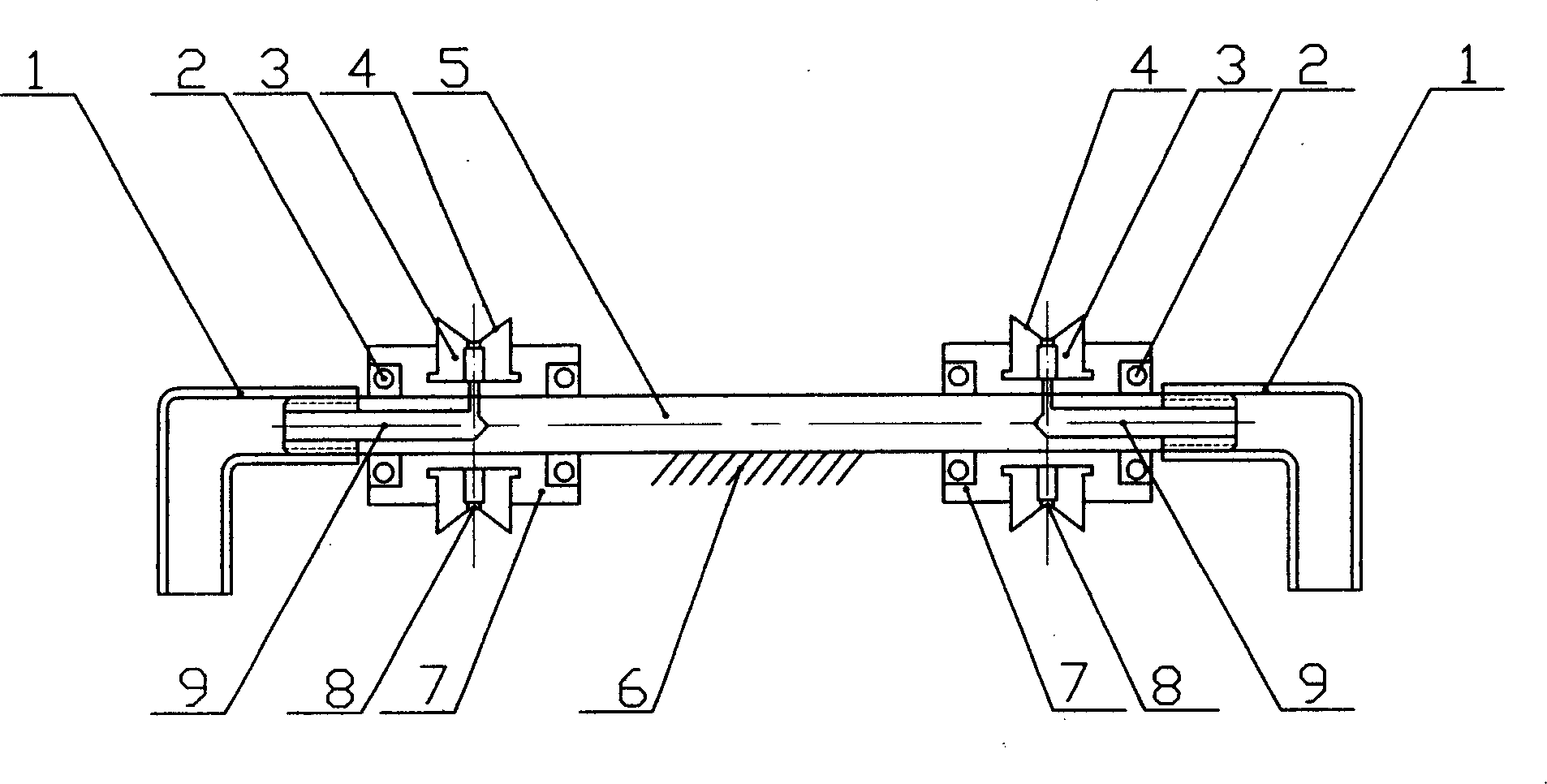
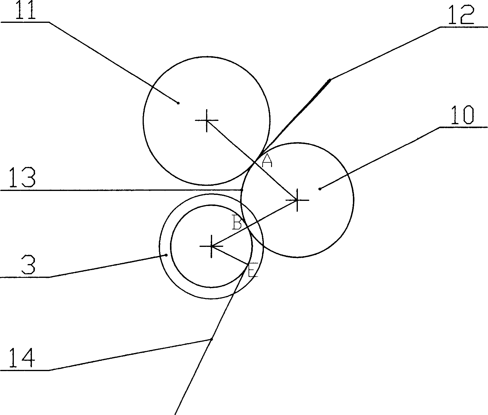
[0015] Such as figure 1 , figure 2 As shown, the negative pressure tube 1 is connected to the central shaft 5, a set of bearings 2 are mounted on the central shaft 5, the yarn guide plate body 7 is mounted on the bearing 2, and the elastic yarn guide plate 3 is mounted on the yarn guide plate body 7. The yarn guide plate 3 is provided with a groove 4, the groove 4 has a number of negative pressure holes 8 at the bottom of the groove, the central shaft 5 is fixed on the spinning frame by the connecting plate 6, and the central shaft 5 is provided with a negative pressure channel 9, which is connected to the negative pressure The pressure hole 8 and the negative pressure pipe 11 constitute a negative pressure system. The yarn guide plate 3 is pressed tightly on the roller 10, the thick sliver 12 passes between the roller 10 and the top roller 11, and is drafted into a thin sliver 13, which is twisted into a thin sliver 13 after passing through the elastic guide plate 3 Yarn 14, is ...


PUM


Abstract

The invention relates to a flexible disc solid compact spinner of spinning machine, wherein one flexible yarn disc is arranged under the lower roller, while it has one circle groove; the section of circle groove is in horn shape, with wide top and narrow bottom, while the groove bottom is semi circle with several passive holes; when the yarn bar is outside the lower roller to enter into the circle groove; since the groove is in horn shape, the bars outside the yarn bar can be entered into the yarn, and when the yarn bar translates in the circle groove, and be compressed via the adsorption function of passive holes, it will be flattened and compacted twisted by spindle, to eliminate the triangle twist area of lower roller, to improve the quality of yarn.

Description

Technical field [0001] The invention relates to a textile machine, in particular to an elastic disc type three-dimensional compact spinning device applied to a spinning frame. Background technique [0002] In the traditional spinning frame spinning process, after the drafted yarn has a certain width and leaves the front roller in a free state, it is immediately processed into yarn. At this time, a spinning yarn is formed in the yarn forming area. In the triangle area, because the loose fibers in the spinning triangle area cannot be well controlled, many fiber hairs around the yarn sliver will be separated in advance and cannot be bundled. The scattered fibers can not be squeezed into the yarn and stick out of the yarn. The formation of "hairiness" in the spinning process seriously affects the quality of the finished yarn and reduces the fiber utilization rate. Therefore, the conveying form of the yarns before twisting must be improved, even if the yarns are ...

Claims


Application Information

Patent Timeline
Patent Type & Authority Applications(China)
IPC IPC(8): D01H5/72
Inventor 刘光容
Owner 绍兴华裕纺机有限公司
Why Eureka
Try Eureka