Electrophoretic display device

A technology for display devices and display screens, which is applied to static indicators, instruments, etc., and can solve problems such as the need for additional time

Inactive Publication Date: 2007-02-07
KONINKLIJKE PHILIPS ELECTRONICS NV
View PDF1 Cites 4 Cited by
  • Summary
  • Abstract
  • Description
  • Claims
  • Application Information

AI Technical Summary

Problems solved by technology

When subsequently switched to the white state, these counterions must be released in time, requiring additional time

Method used


Image

  • Electrophoretic display device
  • Electrophoretic display device
  • Electrophoretic display device

Examples


Embodiment Construction

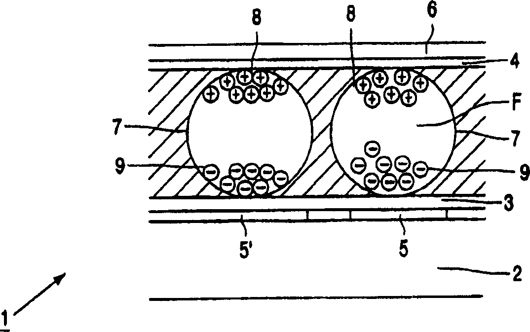
[0032] figure 1Schematic representation of a part of an electrophoretic display device 1, for example a cross-section the size of several display elements, comprising a bottom substrate 2, an electrophoretic film with ink between two transparent substrates 3, 4 (e.g. polyethylene), one of the substrates 3 A transparent pixel electrode 5 is provided, and the other substrate 4 is provided with a transparent counter electrode 6 . Electronic ink comprises a plurality of microcapsules 7 of approximately 10 to 50 microns. Each microcapsule 7 comprises positively charged white particles 8 and negatively charged black particles 9 suspended in a liquid F. When a positive electric field is applied to the pixel electrode 5, the white particles 8 move to the side of the microcapsule 7 directed towards the counter electrode 6 and the display element becomes visible to the observer. At the same time, the black particles 9 move to the opposite side of the microcapsules 7 and cannot be seen...


PUM


Abstract

A display device (1) comprises electrophoretic particles (8,9) and an image screen comprising an array of display elements comprising a pixel electrode and a second electrode. The display device comprises control means (15) for supplying drive signals to the electrodes. In operation the image is displayed in subsequent frames. The control means comprise a row driver (16) and a column driver (10). Preset signals (53) are in operation supplied to the display elements whereby the preset signals applied to display elements alter between subsequent frames. The control means are arranged to change preset signals between frames in a column-to-column scheme. The means for supplying preset signals are arranged such that for the preset signals to at least a part of the image screen comprising a group of columns and rows only one set of data is transferred for the preset signals for said group.

Description

technical field [0001] The present invention relates to a display device comprising electrophoretic particles, a picture screen comprising an array of display elements, wherein the display elements comprise pixel electrodes and a second electrode between which there is a part of electrophoretic particles, and control means which supply drive signals to the electrodes , causing the display element to be in a predetermined optical state corresponding to displayed image information, wherein in operation, an image is displayed in successive frames, the control means includes a row driver and a column driver, and is used to provide a preset signal to the display element means to vary the preset signal applied to the display elements between successive frames. [0002] Such display devices are used for example in monitors, laptop computers, personal digital assistants (PDAs), mobile phones, electronic books, electronic newspapers, electronic magazines. Background technique [000...

Claims


Application Information

Patent Timeline
Patent Type & Authority Applications(China)
IPC IPC(8): G09G3/34
CPCG09G2310/0254G09G3/344G09G2320/0247G09G2310/06G09G2310/068G09G2310/0205G09G2300/08G09G2310/061
Inventor M·T·约翰逊N·埃勒内G·周
Owner KONINKLIJKE PHILIPS ELECTRONICS NV
Why Eureka
Try Eureka