
Track-movable lighting system

A lighting system and track technology, applied in the field of lighting systems, can solve the problems of installation and maintenance difficulties and high energy consumption rate

Inactive Publication Date: 2007-02-14
NEW TECH BANK
View PDF0 Cites 17 Cited by
  • Summary
  • Abstract
  • Description
  • Claims
  • Application Information

AI Technical Summary

Problems solved by technology

[0004] Therefore, traditional lighting equipment has many disadvantages, such as high energy consumption rate and difficult installation and maintenance

Method used


Image

  • Track-movable lighting system
  • Track-movable lighting system
  • Track-movable lighting system

Examples


Embodiment Construction

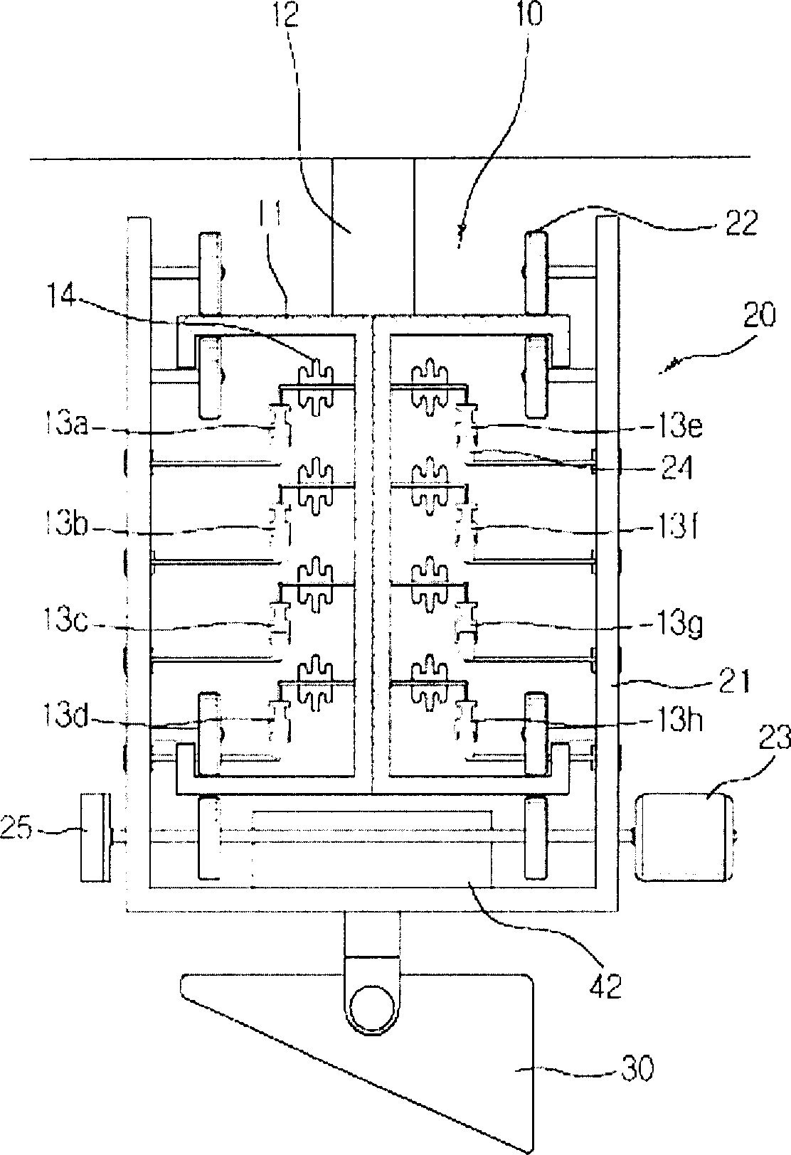
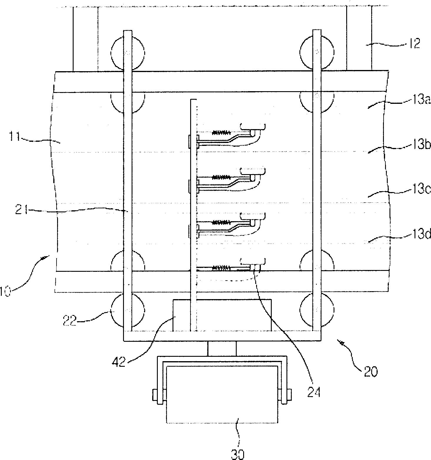
[0018] Next, referring to the accompanying drawings, the lighting system that can move along the track will be described in detail according to the first preferred embodiment of the present invention.

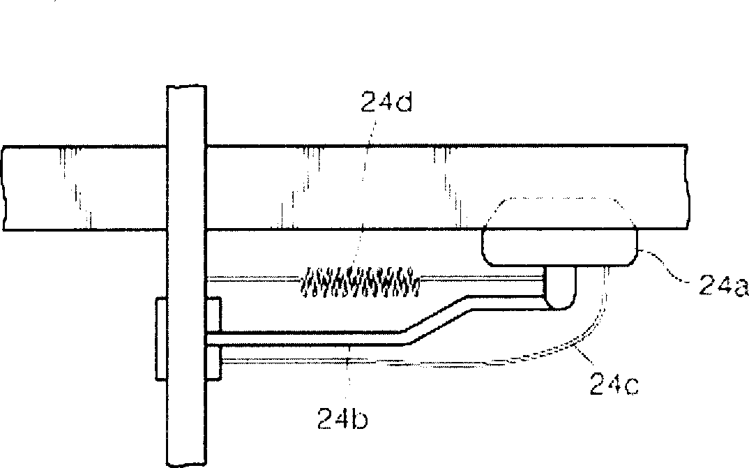
[0019] Such as figure 1 with figure 2 As shown, the track-movable lighting system according to the first preferred embodiment of the present invention includes a track 10 fixedly installed on the ceiling of a building, and multiple lights mounted on the track 10 so as to be able to move along the track 10 through a motor 23. Each transportation unit 20, respectively installed on the transportation unit 20 so as to be able to move with the movement of the transportation unit 20, the lighting device 30, and the control device that controls the movement of the corresponding transportation unit 20 and the corresponding lighting device 30 respectively.

[0020] The track 10 includes a guide rail 11 fixed on the ceiling of a building through a fixing member 12 , and a plurality of ...


PUM


Abstract

A lighting system that can move freely along a rail with a touch rod. This track movable lighting system comprises a track (10) fixedly installed on the building ceiling; a plurality of transport units ( 20); respectively installed on the transportation unit (20) so as to be able to move along with the lighting equipment (30) of the transportation unit (20); and respectively control the movement of the corresponding transportation unit (20) and the corresponding lighting equipment ( 30) The working control device.

Description

technical field [0001] The present invention relates to a lighting system that can move along a track, and more particularly, relates to a lighting system that can move freely along a track with trolley bars. Background technique [0002] Generally, a large number of lighting devices are used in buildings such as indoor stadiums, auditoriums, auditoriums, outdoor stadiums, tunnels, and the like. A common feature of these buildings is that the roofs or ceilings of these buildings are very high. Maintenance of the lighting equipment installed on the ceiling in these buildings is difficult, costly, and expensive due to the difficulty of accessing the lighting equipment. [0003] Therefore, when designing these buildings, in order to reduce the number of maintenance procedures for lighting equipment, designers must install more lighting equipment than is required to illuminate the building, so that even if a few lighting equipment fails or the accumulation of dust causes The o...

Claims


Application Information

Patent Timeline
Patent Type & Authority Applications(China)
IPC IPC(8): F21V21/00B61B5/02B61B13/00B61C13/04F21V21/15F21V21/34H01R25/14H01R41/00
CPCB61B13/00B61B5/02F21V21/15F21V21/34H01R25/14H01R41/00F21V17/02F21V19/04F21V21/14F21V21/35F21K9/238
Inventor 金景焕
Owner NEW TECH BANK
Learn More