Image recording device

A technology for image recording and imaging devices, applied in the direction of electrography, electric recording technology using charge patterns, corona discharge devices, etc., can solve the problems that do not mention the effect of preventing toner from spreading

Inactive Publication Date: 2007-02-21
FUJIFILM BUSINESS INNOVATION CORP
View PDF1 Cites 0 Cited by
  • Summary
  • Abstract
  • Description
  • Claims
  • Application Information

AI Technical Summary

Problems solved by technology

However, in this device, a bias voltage is applied to prevent contamination of the transfer chute, and the effect of preventing toner scattering is not mentioned

Method used


Image

  • Image recording device
  • Image recording device
  • Image recording device

Examples


Embodiment Construction

[0036]

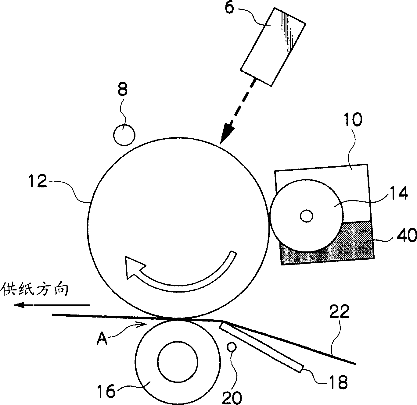
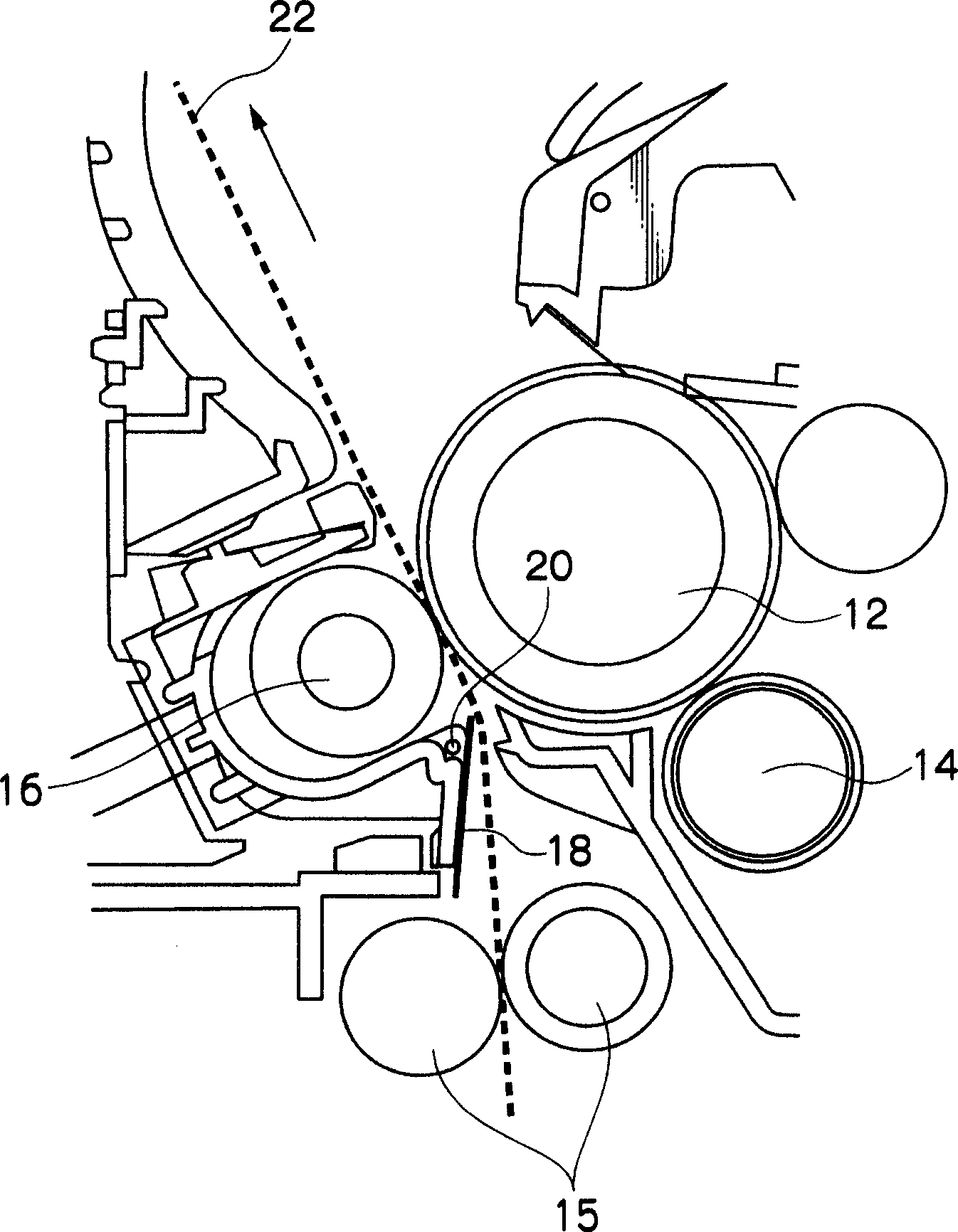
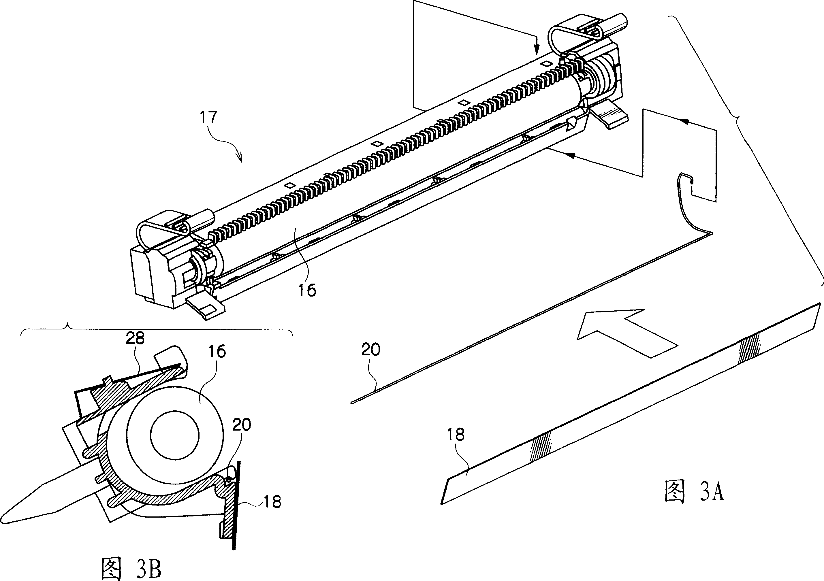
[0037] exist figure 1 The transfer unit of the image forming apparatus according to the first embodiment of the present invention is shown in FIG. 3 .

[0038] Such as figure 1 As shown, the surface of the photosensitive drum 12 is charged in the charger 8 and image-exposed by the ROS 6 . The electrostatic latent image provided by the exposure is developed into a toner image by the developing roller 14 of the developing device 10 . The toner image formed on the photosensitive drum 12 is sandwiched between the transfer roller 16 and the photosensitive drum 12 , and transferred onto the paper 22 to be fed.

[0039] Then, a voltage having the same polarity as that of the toner is applied to a PTB (Pre Transfer Bias) line 20 (ie, a charge generating portion installed so as not to be in contact with the paper 22 ). Thus, an electric field directed from the PTB line 20 to the transfer nip portion A is formed on the toner transferred from the surface of the photosensiti...


PUM


Abstract

An image forming device which transfers a toner image carried on an image carrying body from the image carrying body to a transfer receiving body in a transfer section, the device including a charge producing section provided at an upstream side, in a moving direction of the transfer receiving body, with respect to a position at which the image carrying body and the transfer receiving body oppose each other so as not to be contacted with the transfer receiving body.

Description

technical field [0001] The present invention relates to an image recording device, and more particularly, to an image recording device in which a toner image is transferred and fixed to paper. Background technique [0002] Conventionally, in an image recording apparatus that performs image exposure on the surface of a charged photoreceptor to form a toner image, the toner image is transferred to a transfer body such as paper, and the image is fixed. [0003] In the image recording apparatus described above, the toner is a charged powder, and the transfer body is charged by applying a transfer voltage (transfer bias) having a polarity opposite to that of the toner so that the toner is electrostatically absorbed The toner is transferred onto the transfer body. However, when multiple toners are multi-transferred, a phenomenon in which toners scatter around an image (blur) often occurs, especially in the case of a full-color image. That is, the toner transferred later around t...

Claims


Application Information

Patent Timeline
Patent Type & Authority Applications(China)
IPC IPC(8): G03G15/16G03G15/02G03G15/00
Inventor 赤池彰俊藤田尚寿堀悟
Owner FUJIFILM BUSINESS INNOVATION CORP
Why Eureka
Try Eureka