
Operating microscope

A microscope and surgical technology, applied in the field of surgical microscopes, which can solve the problems of high cost and large bearing size.

Inactive Publication Date: 2007-03-07
OLYMPUS CORP
View PDF3 Cites 19 Cited by
  • Summary
  • Abstract
  • Description
  • Claims
  • Application Information

AI Technical Summary

Problems solved by technology

Therefore, it is likely that the bearing itself is large and expensive

Method used


Image

  • Operating microscope
  • Operating microscope
  • Operating microscope

Examples


Embodiment Construction

[0035] The best mode for carrying out the invention (hereinafter referred to as an embodiment) will now be described with reference to the accompanying drawings.

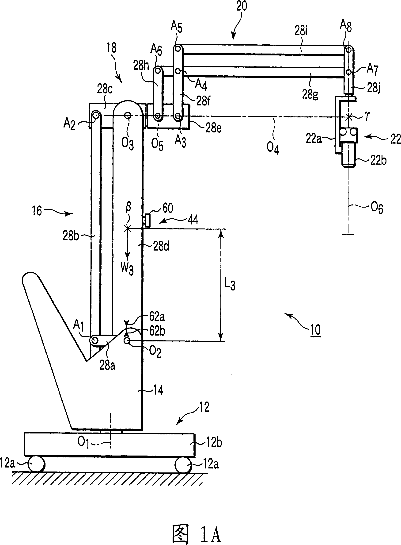
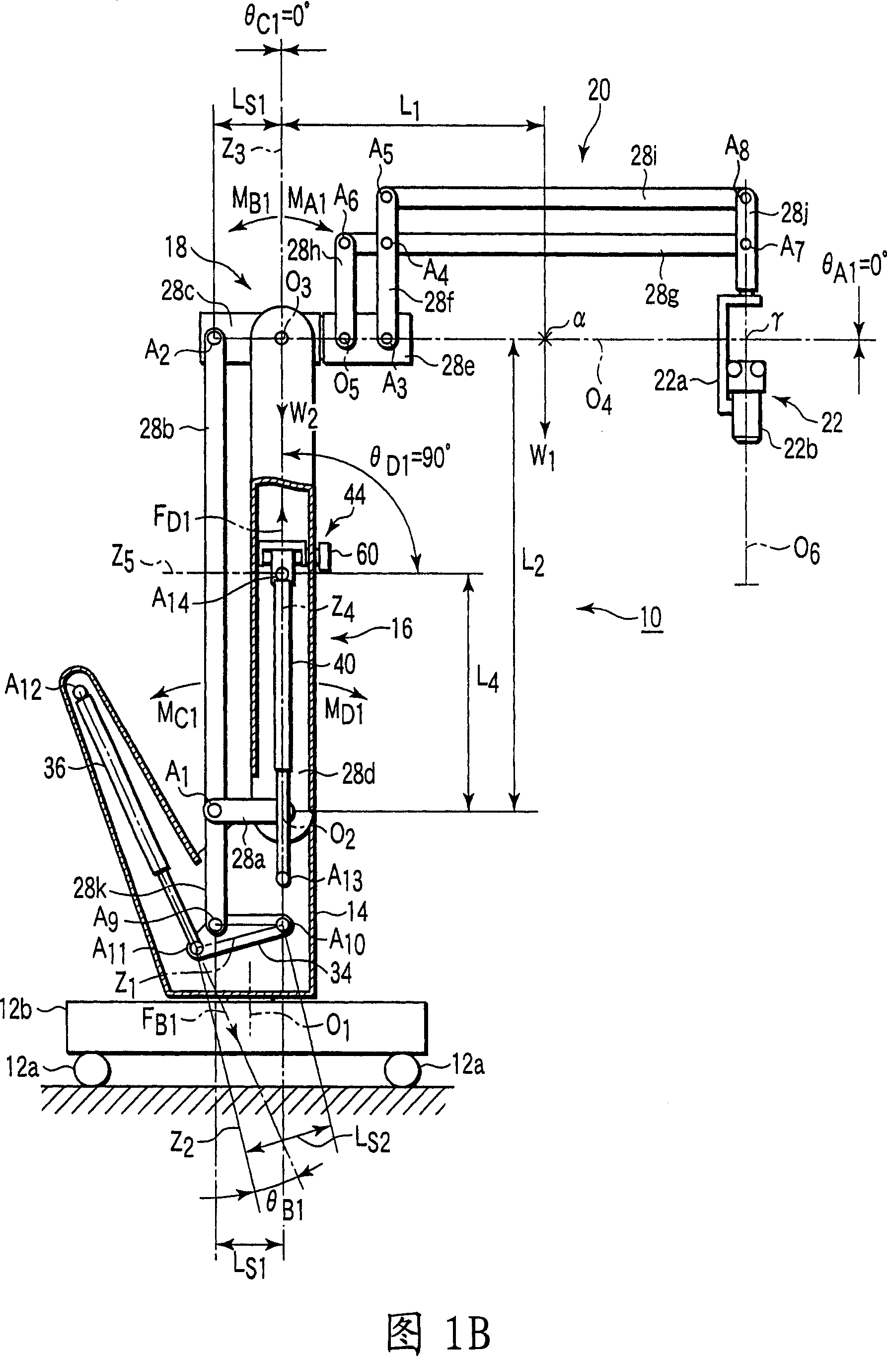
[0036] First, a first embodiment will be described with reference to FIGS. 1A to 5B . Here, the configuration of the surgical microscope 10 will be mainly described with reference to FIGS. 1A and 1B .

[0037] As shown in FIG. 1A , a surgical microscope 10 includes a base 12, a post 14, a first parallelogram linkage (horizontal movement arm) 16, a joint 18, a second parallelogram linkage (vertical movement arm) 20, and Lens barrel part 22 .

[0038] The base 12 is provided with a plurality of casters 12a and a base 12b on the casters 12a, which are placed on the ground and can be switched between a state that can be moved in the operating room and a state that can be fixed. The base body 12b of the base 12 is provided with a first rotation axis O extending in the vertical direction 1 . The lower end of the strut...


PUM


Abstract

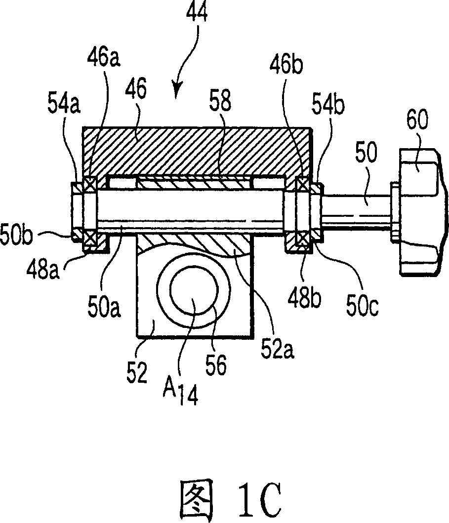
An operating microscope (10), comprising a base (12) installed on a floor surface, a column (14) held on the base rotatably around the rotating vertical axis thereof, a horizontally moving arm (16) held on the column rotatably around a first horizontal rotating axis (O2), a vertically moving arm (20) held on the horizontally moving arm (16) rotatably around a second horizontal rotating axis (O3), a mirror body part (22) supported on the vertically moving arm, an elastic member (40) installed between the column and the horizontally moving arm and canceling the rotating moment of the horizontally moving arm, a pivot (A14) installed in the horizontally moving arm and receiving a force from the elastic member, and a pivot moving mechanism (44) capable of moving the position of the pivot in a direction approximately orthogonal to the longitudinal direction of the horizontally moving arm.

Description

technical field [0001] The present invention relates to surgical microscopes used, for example, in surgical operations. Background technique [0002] For example, Japanese Patent Application Laid-Open No. Hei 7-16239 discloses a surgical microscope. This surgical microscope has a counterweight (balance) type arm frame in which the three-dimensional movement of the lens barrel portion supported on the arm is supported and the overall balance is performed using a counterweight. [0003] Japanese Patent Application Laid-Open No. Sho 57-86806 discloses a surgical microscope having a spring-balanced arm frame in which springs are used for overall balance. The arm frame can make the overall weight or mass of the surgical microscope less than that of a counterweighted arm frame, ie, can make the surgical microscope more compact. Therefore, the surgical microscope has an advantage of improved transportability. [0004] Therefore, the surgical microscope disclosed in Japanese Pate...

Claims


Application Information

Patent Timeline
Patent Type & Authority Applications(China)
IPC IPC(8): A61B19/00G02B21/24A61B90/25G02B21/00
CPCG02B21/0012A61B2019/265A61B19/5223A61B2019/263G02B7/001A61B19/52A61B2090/5025A61B2090/506A61B90/36A61B90/20
Inventor 中村元一野泽纯一
Owner OLYMPUS CORP
Learn More