Eureka AIR delivers breakthrough ideas for toughest innovation challenges, trusted by R&D personnel around the world.

Luminescence indicating apparatus of vehicle

A technology for vehicles and signs, which is applied to display devices, signaling devices, vehicle components, etc., and can solve problems such as poor identification of sign patterns and influence on configuration.

Inactive Publication Date: 2007-03-14
KYMCO
View PDF0 Cites 1 Cited by
  • Summary
  • Abstract
  • Description
  • Claims
  • Application Information

AI Technical Summary

Problems solved by technology

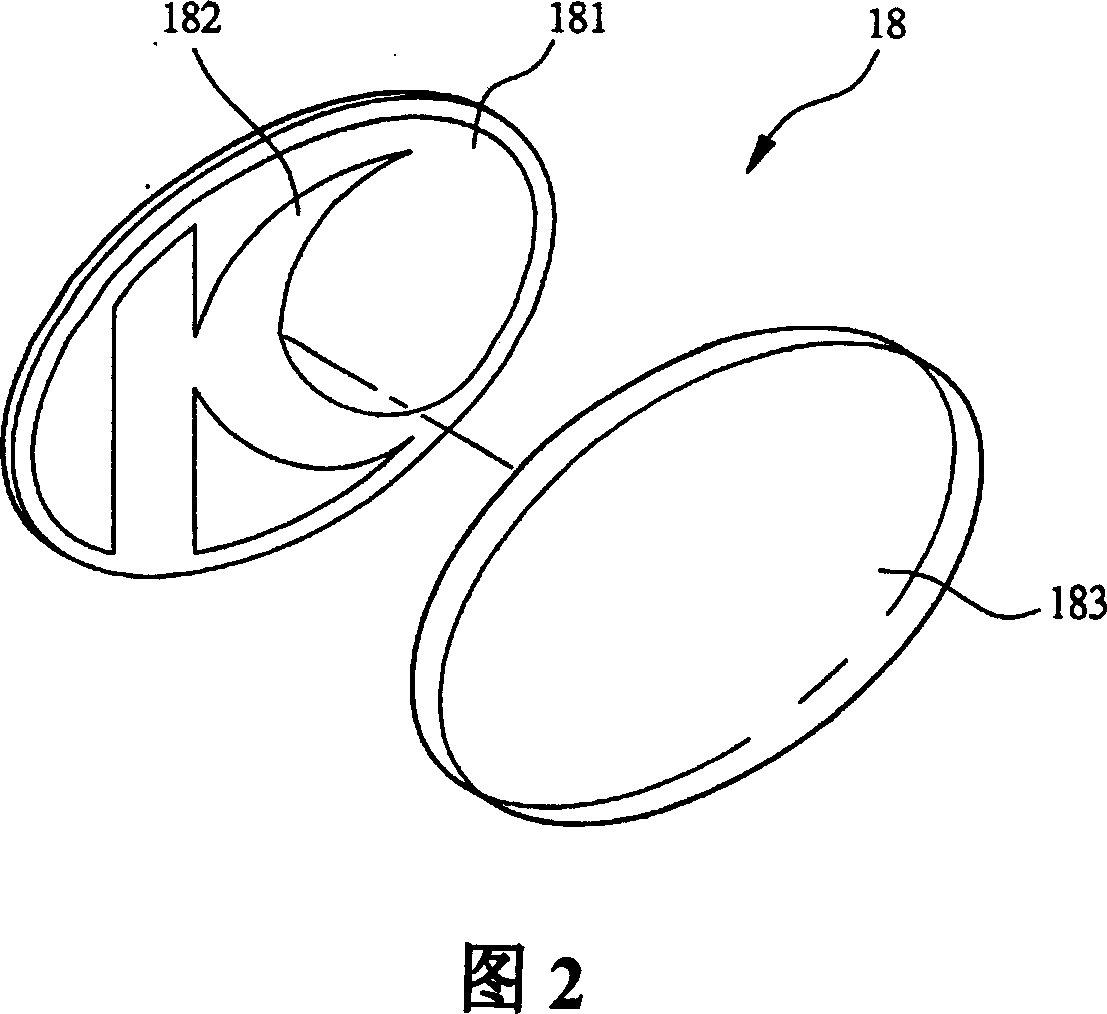
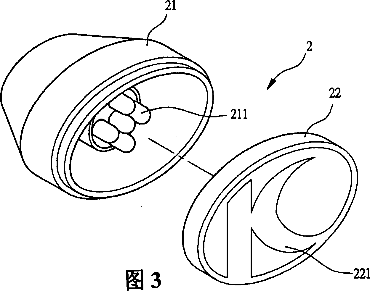
However, due to the luminous properties of the light source unit 211, there will be a beam angle, when the light source unit 211 of the lamp holder 21 is powered on, the light source emitted by the light source unit 21 will directly penetrate the cover 22, and the light source will be concentrated on the lamp cover. 22, so that a bright area is formed in the center of the lampshade 22, and a dark area is formed around it, resulting in poor recognition of the marking pattern 221
[0011] In order to solve this problem, please refer to Fig. 5, the general improvement method is to extend the lampshade 21, under the condition that the light beam angle of the light source unit 211 is maintained at the same angle, the light source irradiation area of ​​the light source unit 211 is enlarged, and the light source is no longer Concentrate in the center of the lampshade 22, so that the marking device 2 can achieve the purpose of uniform luminescence; although the above-mentioned improvement method can prevent the light source from forming a bright area in the center of the marking lampshade 22 and forming a dark area around it, due to the extension of the lamp holder 21, it will affect The configuration of other parts is not a good solution. Therefore, the shortcomings of the known technology are actually a major problem that the industry needs to solve.

Method used


Image

  • Luminescence indicating apparatus of vehicle
  • Luminescence indicating apparatus of vehicle
  • Luminescence indicating apparatus of vehicle

Examples


Embodiment Construction

[0028] In order to understand the structure of the present invention and the effects that can be achieved more easily, please cooperate with the drawings to explain as follows:

[0029] First please refer to FIG. 6 , the marking device 3 of the light emitting marking device for vehicles of the present invention is composed of a lamp holder 31 and a lampshade 32 .

[0030] The lamp holder 31 is a base body, and the lamp holder 31 can be fixed on the front panel or other suitable places of vehicles (such as motorcycles, all-terrain vehicles, etc.), and the front end of the lamp holder 31 can be used for the lampshade 3

[0031] 2, the bottom end of the lamp holder 31 can be fixed for a light source unit 311, and the light source unit 311 is connected to the power supply system of the motorcycle.

[0032] The lampshade 32 shown in Figure 6 is a transparent and light-transmitting cover body, and the lampshade 32 is provided with a marking pattern 321, wherein, a light-scattering m...


PUM


Abstract

The invention relates to a luminescent marker device of vehicles and it is mainly based on setting marker device on the vehicles. The marking device comprises a lamp-base and a lamp-shade. Illuminant unit is installed in the lamp-base and marker drawings are printed on the lamp-shade. Astigmatism convex tablets are fixed on the inside of the lamp-shade correspondingly the position of marker drawings, so the light could diffuse permeating the astigmatism convex tablets when the illuminant unit irradiates the lamp-shade with the help of the astigmatism convex tablets, and avoids illuminant concentrating on the centre of lamp-shade. In addition, the astigmatism effect is better with the help of the lamp-shade which inside not using astigmatism convex tablets are incomplete transparent, so improves the identification of marker device and increases the value of art.

Description

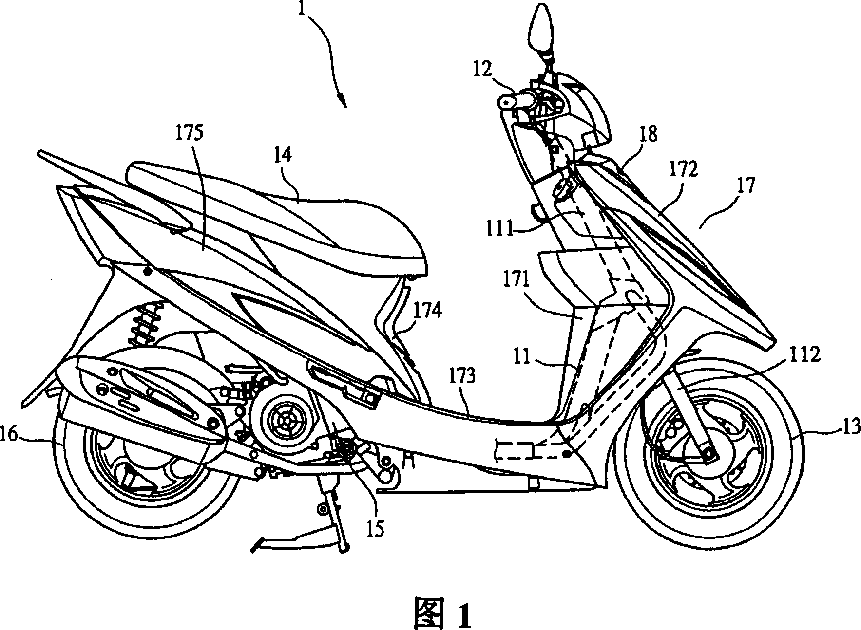
【Technical field】 [0001] The invention relates to a luminous marking device for a vehicle, especially a luminous marking device which can improve identification. 【Background technique】 [0002] In a commercially developed area, what is required is speed and convenience, and the speed and convenience depend on the function of transportation. In addition to public transportation, there are also private transportation, and private transportation is motorcycles. most convenient. The speed and convenience of motorcycles in short distances and light loads are beyond the reach of other means of transportation. Therefore, motorcycles are widely used in today's society, and there is a huge economic market. Because the demand for motorcycles is increasing The bigger the motorcycle industry is, in order to meet the needs of consumers, they have racked their brains to improve the commodity appearance of motorcycles to stimulate consumers' desire to buy. [0003] Known motorcycle 1, pl...

Claims


Application Information

Patent Timeline
IPC IPC(8): B60Q1/56G09F13/04
Inventor 林建成陈益健游见智
Owner KYMCO
Why Eureka
Eureka Blog
Learn More