Plasma fast exciting switch

A technology for exciting switches and plasmas, applied in electronic switches, electrical components, pulse technology, etc., can solve problems such as difficult control, and achieve reliable excitation, rapid opening and closing, and long service life

Inactive Publication Date: 2010-06-23
INST OF PLASMA PHYSICS CHINESE ACAD OF SCI
View PDF3 Cites 0 Cited by
  • Summary
  • Abstract
  • Description
  • Claims
  • Application Information

AI Technical Summary

Problems solved by technology

Under high voltage, the plasma excitation is completed by the coordination of multiple groups of power sources, which is difficult to control

Method used


Image

  • Plasma fast exciting switch
  • Plasma fast exciting switch
  • Plasma fast exciting switch

Examples


Embodiment Construction

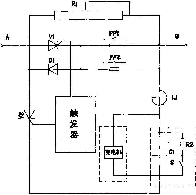
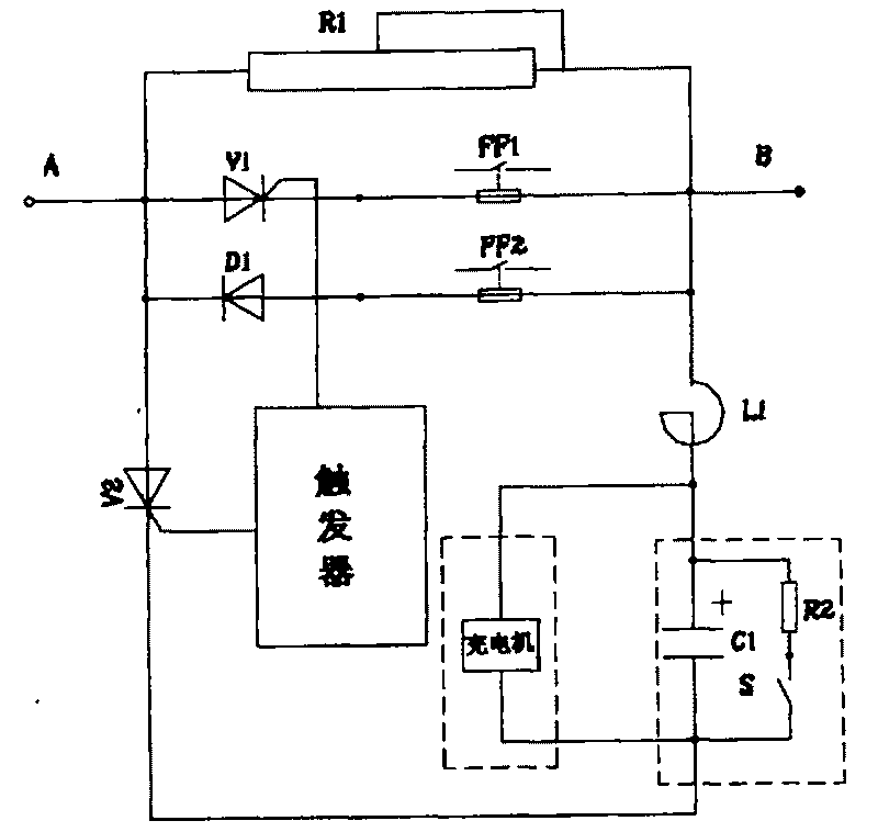
[0011] see figure 1 , figure 2 .

[0012] Principle description:

[0013] First, the charger charges the capacitor C1, and the capacitor C1 is always in a floating charge state. At the same time, the trigger sends a strong pulse to trigger the thyristor V1, so that the thyristor V1 is turned on. , the trigger sends out a group of strong pulses to trigger the thyristor V2, once the thyristor V2 is turned on, the capacitor C1 discharges through the diode D1, so that the voltage across the thyristor V1 is limited to the voltage across the diode D1, and the discharge current of the capacitor C1 is turned on The thyristor V1 is poured back, so that the current flowing through the thyristor V1 is smaller than its own clamping current, so that the thyristor V1 is turned off, and the switch is in an open state at this time. When the thyristor V1 is turned off, the current flowing through the superconducting load in the loop changes instantaneously, generating a high induced potent...


PUM


Abstract

This invention discloses a quick excited switch of plasma characterizing in setting an inverse parallel branch of a diode D1 and a thyristor V1 and a parallel branch of punched resistor R1 between input A and output B, thyristor V2 is serial to capacitor C1 and inductor L1 then parallel between input A and output B, both ends of C1 are parallel to discharge resistor R2 and a charger, a trigger isconnected with the trigger control ends of thyristors V1 and V2, which is a new type of switch without contact point or noise, long life, quick on-off and convenient maintenance.

Description

technical field [0001] The invention relates to a high-power electronic switch, in particular to a plasma rapid excitation switch. technical background [0002] According to the physical design of controlled nuclear fusion engineering, the generation and rapid rise of plasma need to generate ring voltages of 8V and 4V in the vacuum chamber. The cost of the rectifier adopts the switch commutation method to provide the required voltage, so the switch commutation device is installed in the polar field power supply system. In the small-capacity tokamak device, such as HT-7, the storage device is generally used. The generation of plasma current can be realized in the form of capacitive discharge. With the continuous increase of the scale of the tokamak device, if the above method is still used, the required number of energy storage capacitors is large, so most of them adopt the switch commutation method. At present, the superconducting plasma excitation in the controlled nuclea...

Claims


Application Information

Patent Timeline
Patent Type & Authority Patents(China)
IPC IPC(8): H03K17/72
Inventor 汤伦军李定付鹏
Owner INST OF PLASMA PHYSICS CHINESE ACAD OF SCI
Why Eureka
Try Eureka