Automotive brake equipment with valves

A technology of automobile braking and equipment, applied in the direction of brakes, mechanical equipment, hydraulic brake transmissions, etc., can solve the problems of normal characteristics stimulating drivers, etc., and achieve the effect of avoiding invalid time, short control time and avoiding unexpected noise

Inactive Publication Date: 2011-12-14
ROBERT BOSCH GMBH
View PDF0 Cites 0 Cited by
  • Summary
  • Abstract
  • Description
  • Claims
  • Application Information

AI Technical Summary

Problems solved by technology

[0003] The relatively strong pedal response and the relatively loud pulsating noise due to the pressure equalization process from the high-pressure directional valve into the pump suction line do not correspond to the normal behavior of the vehicle's brake system and can therefore irritate the driver

Method used


Image

  • Automotive brake equipment with valves
  • Automotive brake equipment with valves
  • Automotive brake equipment with valves

Examples


Embodiment Construction

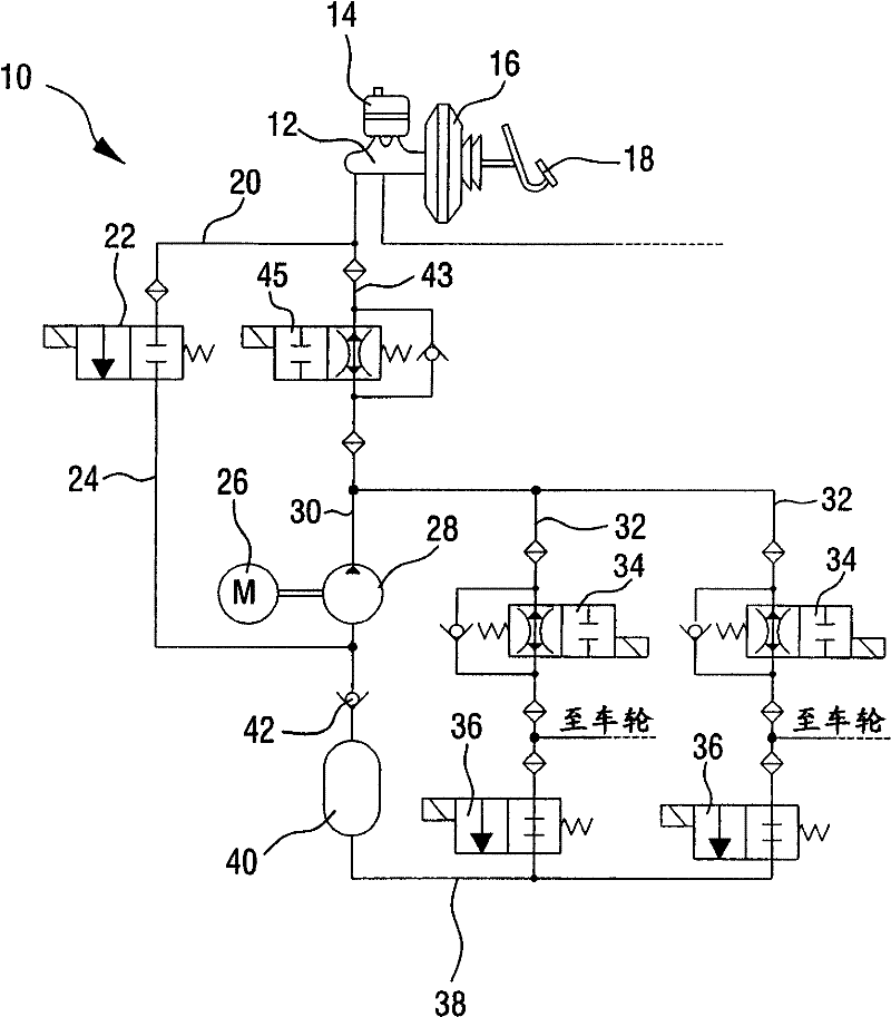
[0020] exist figure 1 A hydraulic circuit diagram of a vehicle brake system 10 is shown in , which has, as main structural components, a master brake cylinder 12 , which has a hydraulic fluid reservoir 14 arranged thereon, a brake booster 16 and a brake pedal 18 . The first and second brake circuits are connected to the master brake cylinder 12, where figure 1 Basically only the first brake circuit can be seen in it. In this brake circuit, a line 20 leads to a high-pressure directional valve 22 , behind which a suction line 24 leads to a pump 28 driven by an electric motor. The fluid conveyed in this way can be conveyed by means of a pump 28 into a pipe 30 , to which two parallel pipes 32 are connected. In each parallel line 32 a two-position / two-way valve 34 is provided, the open position of which is damped. The two-position / two-way valve 34 leads to the wheel (not shown) with the associated wheel brake cylinder and also leads to the line 32 , in which the two-position / tw...


PUM


Abstract

In the vehicle brake system (10) having a valve (22) arranged between the first and second chambers (20, 24), through which the first chamber (20) can be selectively The fluid is guided into the second chamber (24) and the valve is equipped with a pre-stage (50, 52) and a main stage (54, 56) for guiding the fluid, according to the invention the pre-stage (50, 52) outside The control opening is configured and the main stage (54, 56) is configured to automatically open when the preceding stage (50, 52) is opened.

Description

technical field [0001] The invention relates to a vehicle brake system having a valve arranged between a first chamber and a second chamber, through which fluid can be selectively guided from the first chamber into the second chamber and The valve is equipped with a pre-stage and a main stage for guiding fluid. Background technique [0002] In modern vehicle brake systems, self-priming pumps are used which suck fluid out of a storage container, which is arranged, for example, on the master brake cylinder and which can be supplied onwards, for example, to build up brake pressure at the wheel brakes. Between the storage vessel and the suction side of the pump there is a high pressure selector valve (HSV) which selectively closes off the line from the storage vessel to the pump suction side. When the high-pressure reversing valve arranged in this way is closed, the self-priming pump can evacuate the area between the high-pressure reversing valve and the pump inlet in a certain...

Claims


Application Information

Patent Timeline
Patent Type & Authority Patents(China)
IPC IPC(8): B60T11/232
CPCF16K31/408B60T8/5025B60T8/363
Inventor T・米希尔
Owner ROBERT BOSCH GMBH
Why Eureka
Try Eureka