Long travel high capacity friction draft gear assembly

A technology of friction clutch and buffer device, which is applied in the direction of traction device, transportation and packaging, railway car body parts, etc., and can solve the problem that the buffer stroke is only 3.25 inches

Inactive Publication Date: 2007-04-04
WESTINGHOUSE AIR BRAKE TECH CORP
View PDF1 Cites 1 Cited by
  • Summary
  • Abstract
  • Description
  • Claims
  • Application Information

AI Technical Summary

Problems solved by technology

[0011] However, with the existing 24.625" long

Method used


Image

  • Long travel high capacity friction draft gear assembly
  • Long travel high capacity friction draft gear assembly
  • Long travel high capacity friction draft gear assembly

Examples


Embodiment Construction

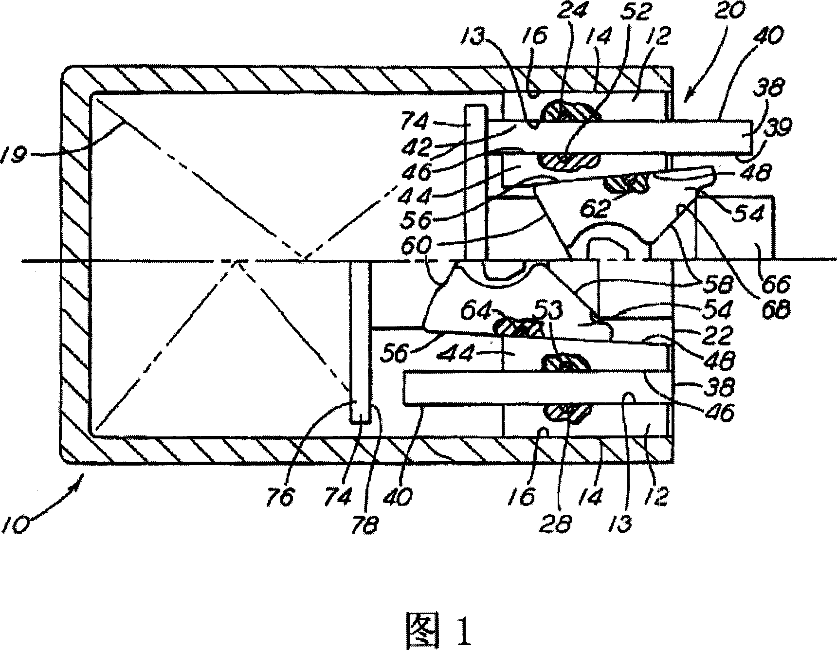
[0024] Description will now be made with reference to the accompanying drawings. As shown in FIG. 1, an improved friction clutch device 20 is used to absorb heat energy in a friction clutch type damper device 10, which is used in a railway locomotive (not shown). As shown in the prior art, this heat energy is generated during the assembly process of the railway vehicle or during the movement of the railway vehicle on the rails.

[0025] The friction clutch device 20 includes a pair of static outer members 12 each having an inner surface 13 and an outer surface 14 . The outer surface 14 engages its diametrically opposite inner surface 16 of the bumper housing 18 near the open end 22 .

[0026] The friction clutch device 20 further includes a pair of moving members 38, each of which has at least a predetermined portion of an outer surface 40 frictionally engaged with the inner surface 13 of its respective outer static member 12 to absorb The first part of the heat. The moving...


PUM

PropertyMeasurementUnit
Tilt angleaaaaaaaaaa

Abstract

A friction clutch type draft gear assembly (10) includes a housing (18) having an open front end (22) and a closed rear end forming a ledge (21) for enabling a longer buff and draft travel while fitting into a 24.625 inch draft gear pocket. A friction clutch mechanism (20) includes a pair of outer stationary plate members (12), a pair of movable plate members (38), a pair of inner stationary plate members (44) having an inner surface (48) which is tapered at an angle of approximately 4.5 DEG , a pair of wedge shoe members (54) having an upper surface (58) which is tapered relative to a longitudinal axis of the friction clutch mechanism (20), and a center wedge member (66) which includes a pair of correspondingly tapered surfaces (68). The tapered upper surface (58) of the pair of wedge shoe members (54) is tapered at an angle of approximately 49.0 DEG -50.0 DEG . The pair of tapered surfaces (68) of the center wedge (66) is tapered at an angle of about 49.5 DEG.

Description

technical field [0001] The invention relates to a friction clutch buffer device for dissipating and absorbing impact loads for railway vehicles, in particular to a friction clutch device comprising a housing and a friction clutch device, which has a longer stroke and can reduce the impact of reaction force and promote the smooth running of railway vehicles , a buffer device that improves the overall efficiency of the buffer. Background technique [0002] A buffer device that utilizes a friction clutch device to absorb heat generated by a railway vehicle during operation is widely used in the railway vehicle industry. The cushioning device is located in a long cavity, which is located in the center beam of the railway vehicle in the axial direction, at the rear end of the connecting device. [0003] Friction clutch dampers absorb most of the compressive and tractive forces generated during the operation of a rail vehicle. During the normal running of the railway vehicle, th...

Claims


Application Information

Patent Timeline
IPC IPC(8): B61G9/10
Inventor 迈克尔·E·林霍华德·R·索末菲
Owner WESTINGHOUSE AIR BRAKE TECH CORP
Why Eureka
Try Eureka