Vehicle lamp

A technology for lamps and vehicles, applied in the direction of headlights, road vehicles, vehicle parts, etc., can solve the problems of increasing the size in the left and right directions, widening the lateral width of the light distribution pattern, unable to form a point-shaped light distribution pattern, etc. Effect of left and right dimensions

A technology for lamps and vehicles, applied in the direction of headlights, road vehicles, vehicle parts, etc., can solve the problems of increasing the size in the left and right directions, widening the lateral width of the light distribution pattern, unable to form a point-shaped light distribution pattern, etc. Effect of left and right dimensions

CN1948821AInactive Publication Date: 2007-04-18STANLEY ELECTRIC CO LTD

Image

  • Vehicle lamp
  • Vehicle lamp
  • Vehicle lamp

Examples


Embodiment Construction

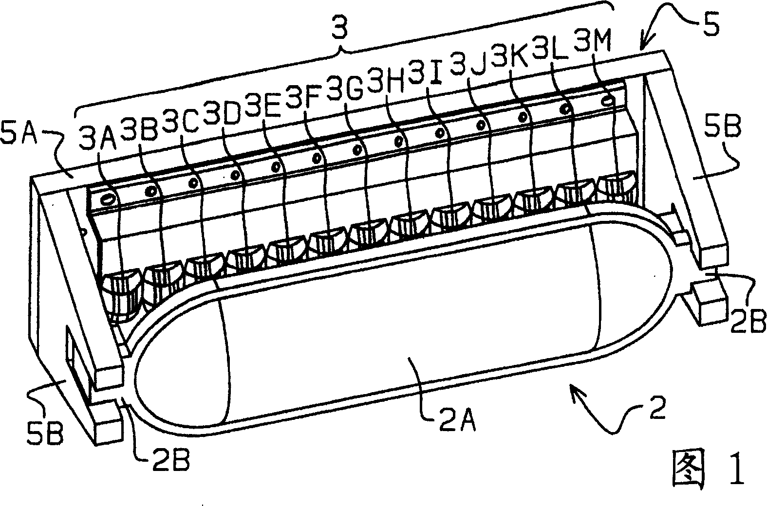
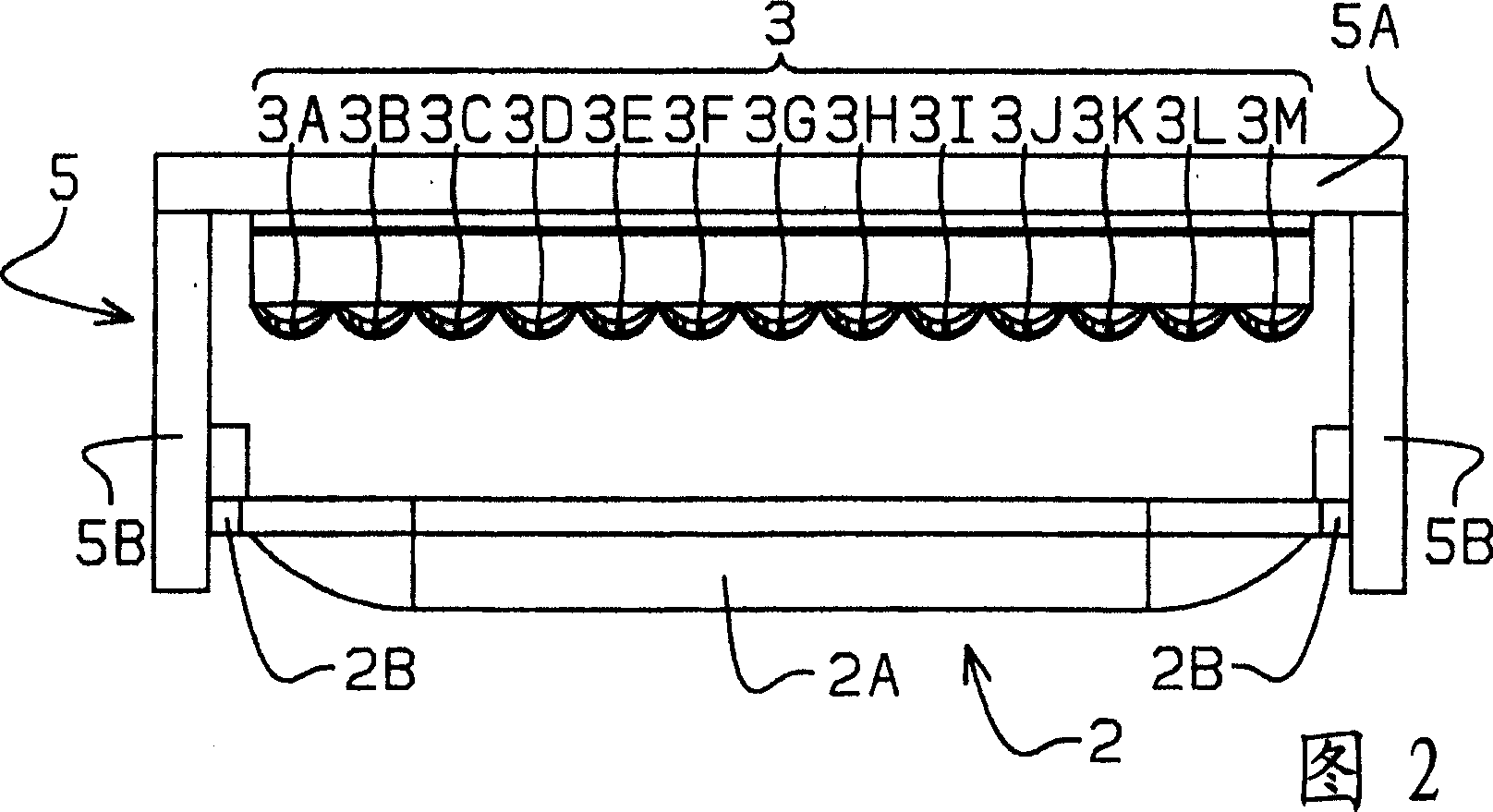
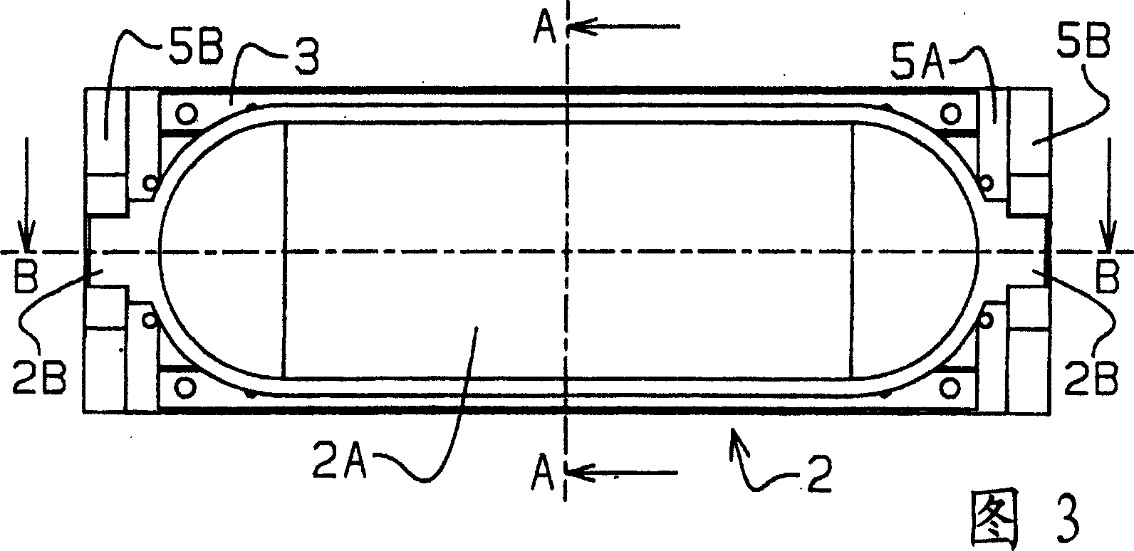
[0045] Next, a first embodiment of the vehicle lamp of the present invention will be described. 1 is a perspective view of the vehicle lamp according to the first embodiment viewed from the front side, the left side and the upper side, FIG. 2 is a top view of the vehicle lamp according to the first embodiment, and FIG. 3 is a front view of the vehicle lamp according to the first embodiment. 4 is a right side view of the vehicle lamp according to the first embodiment. 5 is an A-A sectional view of the vehicle lamp of the first embodiment shown in FIG. 3 , FIG. 6 is an enlarged view of the vehicle lamp of the first embodiment shown in FIG. 5 , and FIG. 7 is a view of the first embodiment of FIG. 3 . 8 is an enlarged view of the vehicle lamp according to the first embodiment shown in FIG. 7 .

[0046] The vehicle lamp according to the first embodiment is arranged inside the front surface of the vehicle so as to face the front of the vehicle in order to irradiate the irradiation ...


PUM


Abstract

Provided is a vehicle lamp to reduce the horizontal size of a cylindrical lens and illuminate the front of a vehicular lighting fixture brightly. The vehicular lighting fixture comprises a plurality of LEDs (1A, 1B, 1C, ..., 1M) arranged on a straight line (L) extending in a horizontal direction, and a cylindrical lens (2) for condensing light emitted forward from the LEDs (1A, 1B, 1C, ..., 1M) in the vertical direction of the vehicular lighting fixture. In this vehicular lighting fixture, condensing lens sections (3A, 3B, 3C, ..., 3M) that exhibit a higher degree of light condensing in the horizontal direction than in the vertical direction are provided between the cylindrical lens (2) and the respective LEDs (1A, 1B, 1C, ..., 1M).

Description

technical field [0001] The present invention relates to a lamp for vehicles, which has a plurality of light-emitting elements arranged on a straight line extending in the left-right direction, and is provided with a cylindrical lens that directs the light radiated from the plurality of light-emitting elements to the front side up and down. Focusing light in a direction, in particular, relates to a vehicle lamp capable of reducing the lateral dimension of a cylindrical lens and brightly illuminating the front side of the vehicle lamp. [0002] More specifically, the present invention relates to a vehicle lamp that irradiates arbitrary light such as infrared rays or visible light to the front side of the vehicle lamp. Background technique [0003] Conventionally, there is known a vehicle lamp in which a plurality of light emitting elements are arranged in a straight line and a cylindrical lens is provided. As examples of such vehicle lamps, there are, for example, those descr...

Claims


Application Information

Patent Timeline
18 Apr 2007
Publication
CN1948821A
IPC
F21S8/10; F21V5/04; F21W101/02; F21W107/10
CPC
F21S41/143; F21S41/151; F21S41/26; F21S41/285; F21S41/295
Inventors
大野雅典; 大束英雄