Display driving circuit

A display driver and circuit technology, which is applied in the direction of electric light circuit arrangement, electric light source, static indicator, etc., can solve the problems of increasing the hardware scale and cost of the display device, and the logic circuit scale, and achieve the realization of the hardware scale and cost. drop, reduce the amount of logic, and achieve the effect of power saving

Inactive Publication Date: 2007-04-18
RENESAS ELECTRONICS CORP
View PDF1 Cites 4 Cited by
  • Summary
  • Abstract
  • Description
  • Claims
  • Application Information

AI Technical Summary

Problems solved by technology

However, in the second method, since it is necessary to hold all the data of the histogram of the image for control, the scale of the logic circuit used for the histogram increases, and corresponding hardware is required.
That is, it leads to an increase in the hardware scale and cost of the display device.

Method used


Image

  • Display driving circuit
  • Display driving circuit
  • Display driving circuit

Examples


Embodiment approach 1

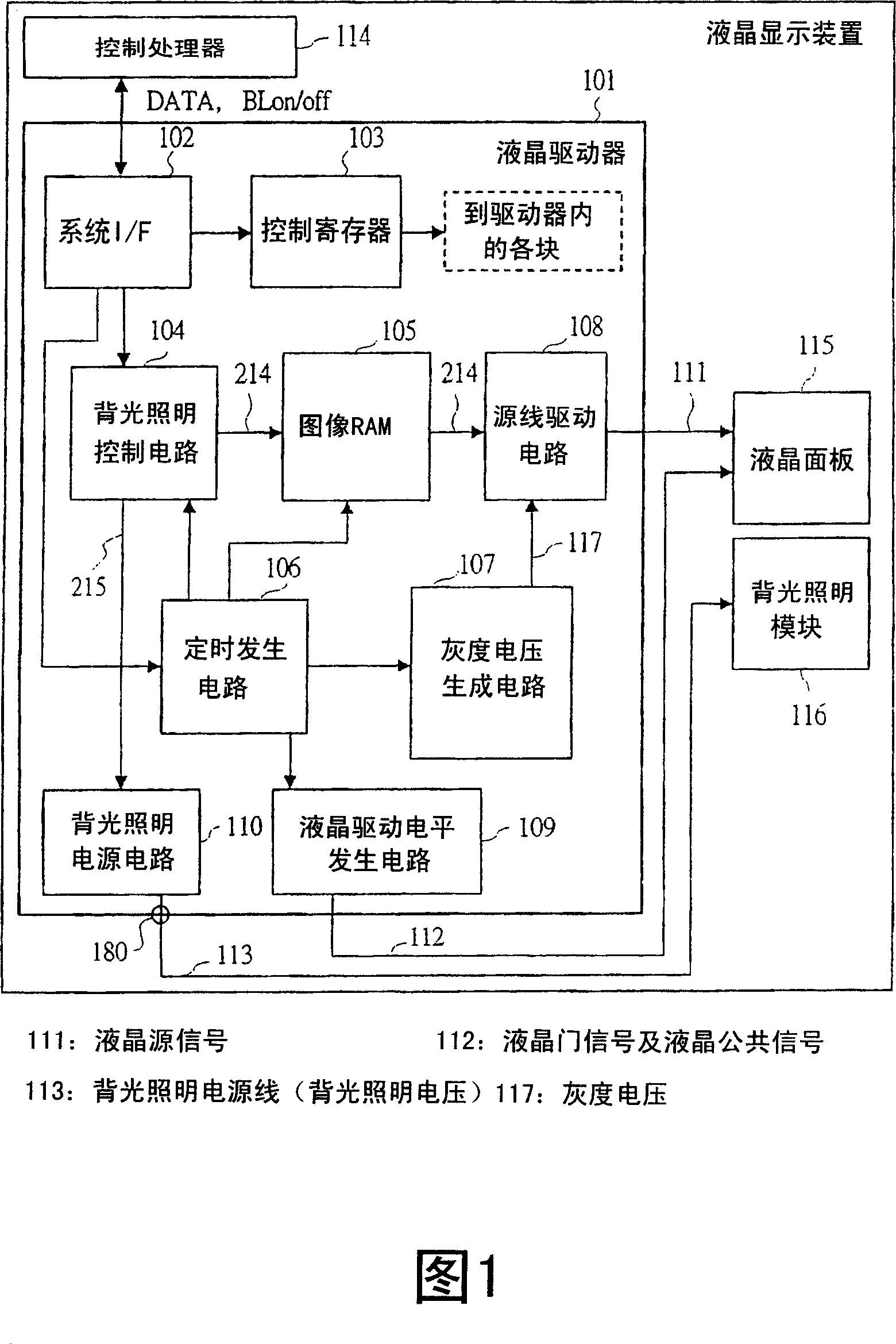
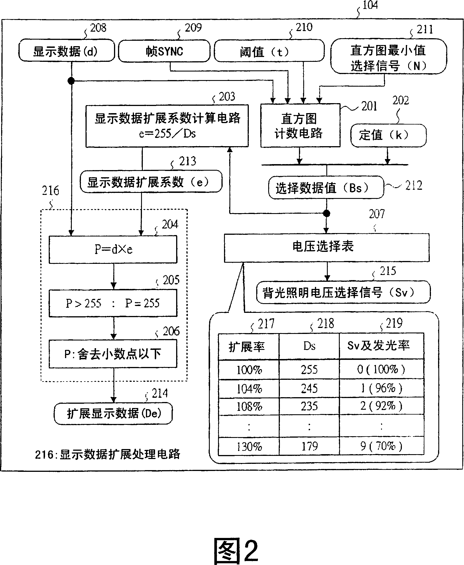
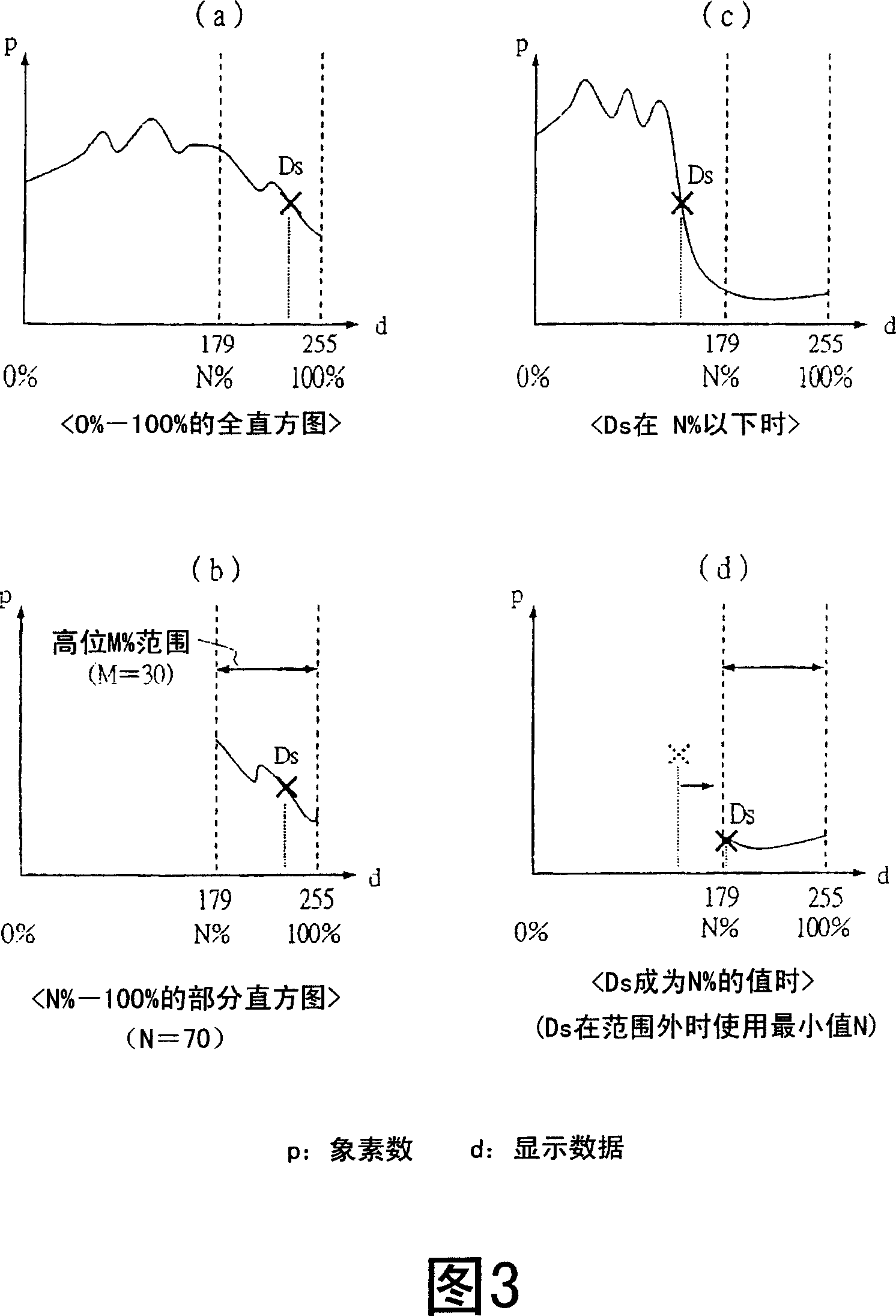
[0044] FIG. 1 shows the configuration of a liquid crystal display device including a liquid crystal driver 101 according to Embodiment 1 and its surroundings. FIG. 2 shows the configuration and processing of the backlight control circuit 104 in the liquid crystal driver 101 . FIG. 3 shows a process of using a partial histogram as characteristic control in the liquid crystal driver 101 . FIG. 4 is a flow of control processing in the liquid crystal driver 101 . FIG. 6 schematically shows the structure of backlight illumination and display in this liquid crystal display device.

[0045] In FIG. 1 , the present liquid crystal display device has a control processor 114 , a liquid crystal driver 101 , a liquid crystal panel 115 , and a backlight module 116 . The control processor 114 controls the entire liquid crystal display device including the liquid crystal driver 101 . This liquid crystal display device is, for example, a liquid crystal display mounted on a mobile phone or t...

Embodiment approach 2

[0081] Embodiment 2 will be described below. FIG. 5 shows a liquid crystal display device including a liquid crystal driver 101B of Embodiment 2 and its surroundings. Compared with Embodiment 1, the backlight power supply circuit 110 is not provided inside the liquid crystal driver 101B, instead, a backlight external power supply circuit 501 equivalent to the function of the backlight power supply circuit 110 is added outside the liquid crystal driver 101B and inside the liquid crystal display device. A backlight control signal 502 (corresponding to the above-mentioned backlight voltage selection signal 215 ) is output from the liquid crystal driver 101B, and the backlight external power supply circuit 501 is controlled in the same manner as in the first embodiment. The control itself of the backlight power saving function is the same as that of the first embodiment.

[0082] Based on information from the backlight control circuit 104 , a backlight control signal 502 is gener...

Embodiment approach 3

[0085] Next, Embodiment 3 will be described using FIGS. 7 to 9 . In Embodiment 1 above, by not having a histogram for all pixel values ​​(0 to 255), but having a histogram for a part of high-order values ​​(for example, 183 to 255), it is possible to reduce the circuit scale and realize practical use. The amount of light emitted by the backlight is controlled. In addition, in the liquid crystal driver of the third embodiment, instead of fixing the upper limit of the histogram storage target at 255 (pixel value), the control is made more flexible by setting both the upper limit and the lower limit. And can easily correspond to displays with different gamma curves.

[0086] FIG. 7 shows a block configuration of a histogram counting circuit 601 (a circuit corresponding to the above-mentioned 201 ) in the third embodiment. The histogram counting circuit 601 includes: an item data generating circuit 602 , a plurality of comparators A 603 , a plurality of counters 604 , a pluralit...


PUM


Abstract

In a display driving circuit according to the present invention, not all the pixel values (example : 0~255) but only the values (example : 179~255) of the significant partial range (N~100%) have data of histogram of pixels of an image as a partial histogram, and when the pixel (Ds) at the significant t% rank order of the entire histogram is within the range of the partial histogram, the display driving circuit performs its operation in the same manner as in the case where it has the entire histogram, and when the pixel (Ds) is out of the range, the display driving circuit uses the range minimum value (N) in the place of the pixel of the significant t% rank order and performs its operation.

Description

technical field [0001] The present invention relates to the technology of display devices such as liquid crystal displays and their drive circuits, and in particular to the control technology of lighting and display on display devices with lighting units such as backlights. Background technique [0002] In recent years, liquid crystal displays are mounted on battery-driven information devices such as mobile phones. These displays are almost all transmissive and semi-transmissive which require backlighting. Currently, most of the power consumption of liquid crystal displays is the power consumption of backlighting. Therefore, a method for reducing power consumption of the backlight is required. In particular, a mobile phone equipped with a liquid crystal display needs to be driven by a battery for a long time in a state where the liquid crystal display is displayed so that moving images such as television can be viewed. [0003] As a method of reducing backlight electric p...

Claims


Application Information

Patent Timeline
Patent Type & Authority Applications(China)
IPC IPC(8): G09G3/36G09G3/34G09G3/20G02F1/133H05B37/02
CPCG09G2320/0247G09G2360/16G09G2360/18G09G2330/021G09G2320/0653G09G2320/0673G09G2320/04G09G3/3406G09G2320/0646G09G2320/0271G09G3/3611G09G3/2092G09G2320/0633G09G3/36G02F1/133G09G3/20
Inventor 黑川能毅工藤泰幸熊谷俊志坂卷五郎
Owner RENESAS ELECTRONICS CORP
Why Eureka
Try Eureka