Electronic flight instrument displays

a flight instrument and display technology, applied in the field of electronic flight instrument displays, can solve the problems of reducing the utility of the flight path marker, reducing the use of the primary flight display, and not further processing information based on, so as to reduce the cost, weight and power consumption, and enhance the pilot's situational awareness.

Inactive Publication Date: 2006-01-10
CHELTON FLIGHT SYST INC
View PDF31 Cites 59 Cited by
  • Summary
  • Abstract
  • Description
  • Claims
  • Application Information

AI Technical Summary

Benefits of technology

[0011]The present invention is directed to novel primary flight displays, moving map displays and engine parameter displays for aircraft cockpits. These displays process data gathered from various aircraft sensors and, using a variety of electronic databases, generate intuitive symbols that aid the pilot. The present invention also uses various novel algorithms that allows use of data gathered from inexpensive sensors to derive parameters that normally require far more expensive sensors.
[0012]The primary flight display of the present invention discards the old-style two dimensional attitude indicator / flight director symbology in favor of creating a virtual three-dimensional world. The display makes use of a terrain database and, optionally, an obstruction database. Terrain and obstructions are presented three-dimensionally as the background of the primary flight display. Navigational symbology is likewise three-dimensional. By presenting a flight path marker to the pilot in conjunction with a three-dimensional display, the advantages of a HUD are realized on a panel-mounted electronic screen at far less cost, weight and power consumption. Unlike a HUED, the primary flight display of the present invention has the further advantage of being able to show a three-dimensional world for navigation in all weather conditions. In one embodiment, the primary flight display further includes a small, selected-waypoint focused moving map with course line for all-aspect situational awareness. In one particularly low-cost embodiment for light aircraft, aircraft pitch and roll become fixed and the primary flight display becomes a forward looking situational awareness display that intuitively presents the location of terrain, obstructions, and navigational points in three dimensional space in front of the aircraft.
[0013]The moving map of the present invention is similar to prior art moving maps with the exception that it imports aircraft altitude information and displays relevant obstruction and airspace information to the pilot. For example, by taking aircraft altitude into account, the moving map of the present invention can selectively display only terrain that is above and slightly below current aircraft altitude. In this way, non-critical information is not constantly displayed to distract the pilot, a distinct advantage over moving maps that use bit-mapped cartography. Likewise, obstructions to navigation can be selectively displayed depending upon whether they are a hazard to navigation at a particular aircraft altitude. Airspace limits can be drawn in different colors depending upon whether the aircraft will enter that airspace at its current altitude. By automatically displaying, not displaying, and symbolically coloring navigational symbols, the pilot's situational awareness is enhanced.
[0014]The engine parameter display of the present invention also includes enhancements that aid pilot situational awareness. Engine parameters are displayed as pie wedges with a leading needle and an integral digital display. However, the color of the entire pie wedge is keyed to the relationship of the selected engine parameter to its limit conditions. Normally the pie wedges are green to indicate a normal condition. As the engine parameter reaches its limit, the pie wedge's color changes from green to yellow and then to red to indicate progressively worsening conditions. An alternative, bar-type display is particularly useful for comparatively displaying multiple readings from the, same type of sensor, such as multiple cylinder head temperature or exhaust gas temperature readings from a multi-cylinder piston engine. As with the pie wedge display, the color of the bar indicates that parameter's condition. Furthermore, the highest reading is given a three-dimensional “unpushed” button look to make it stand out from the other bars. Likewise the lowest reading is given a three-dimensional “pushed” button look. Finally, certain parameters that are advantageously trended can be displayed in a recording chart time-lapse style so that deviations become immediately apparent.

Problems solved by technology

Nevertheless, despite the fact that electronic screens do not have the same physical limitations as mechanical instruments, current primary flight displays retain archaic two-dimensional symbology which does not impart information to the pilot in a natural manner.
Thus, use of current primary flights displays still requires extensive training and practice and is subject to the same misinterpretation errors as mechanical instruments.
However, showing a flight path marker on such traditional two-dimensional displays greatly reduces the utility of the flight path marker, which is preferably used in conjunction with a three-dimensional background.
However, current moving map systems only display information and do not further process information based upon altitude to show the pilot immediate threats to flight safety.
However, prior art engine parameter displays still require the pilot to compare the position of the analog pointers or pie wedges to the previously mentioned warning arcs or markers to ascertain out of limit conditions.
In addition, prior art engine parameter displays, which display real time engine parameters, suffer from the same drawbacks as mechanical gauges when it comes to detection of trends.

Method used


Image

  • Electronic flight instrument displays
  • Electronic flight instrument displays
  • Electronic flight instrument displays

Examples


Embodiment Construction

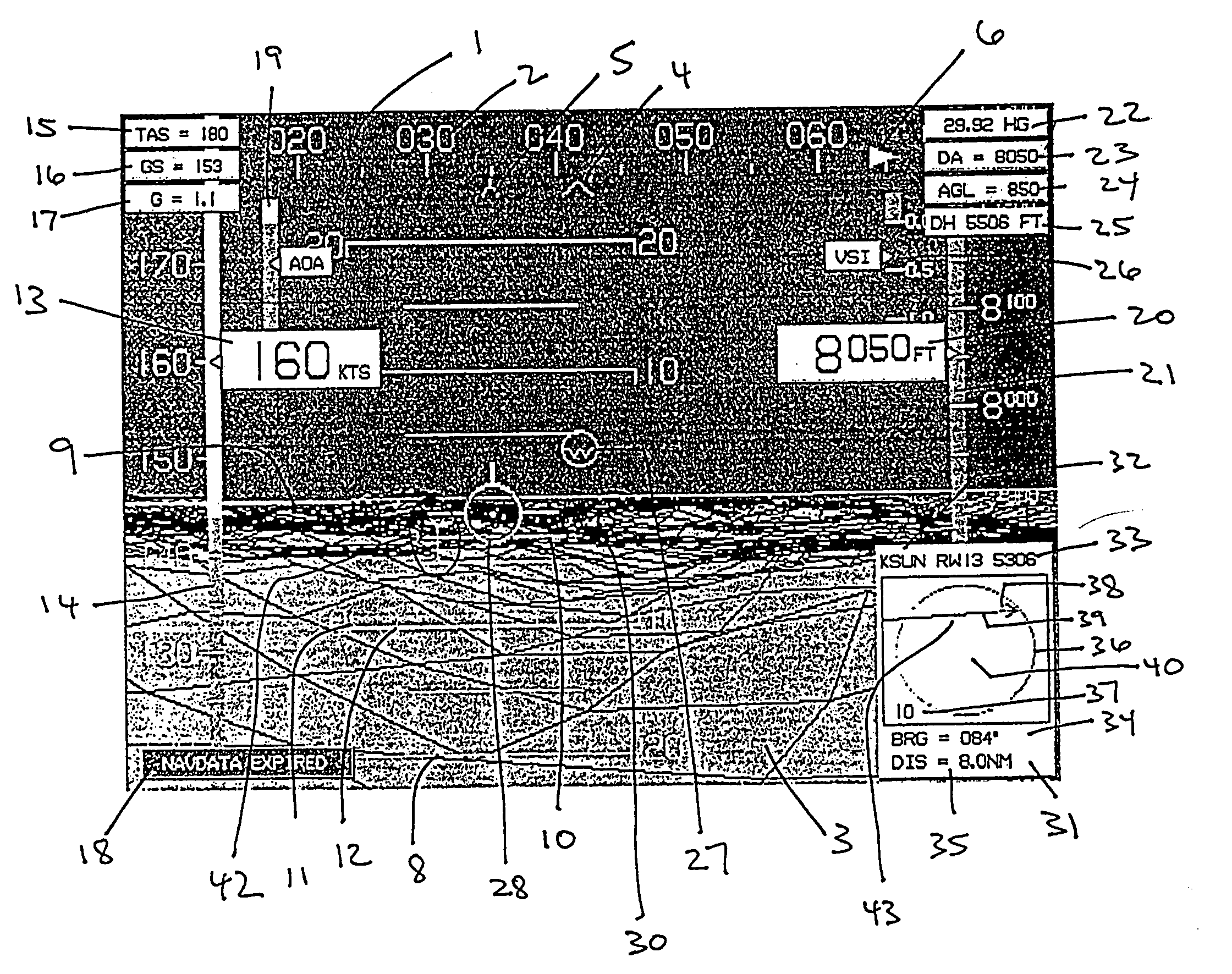
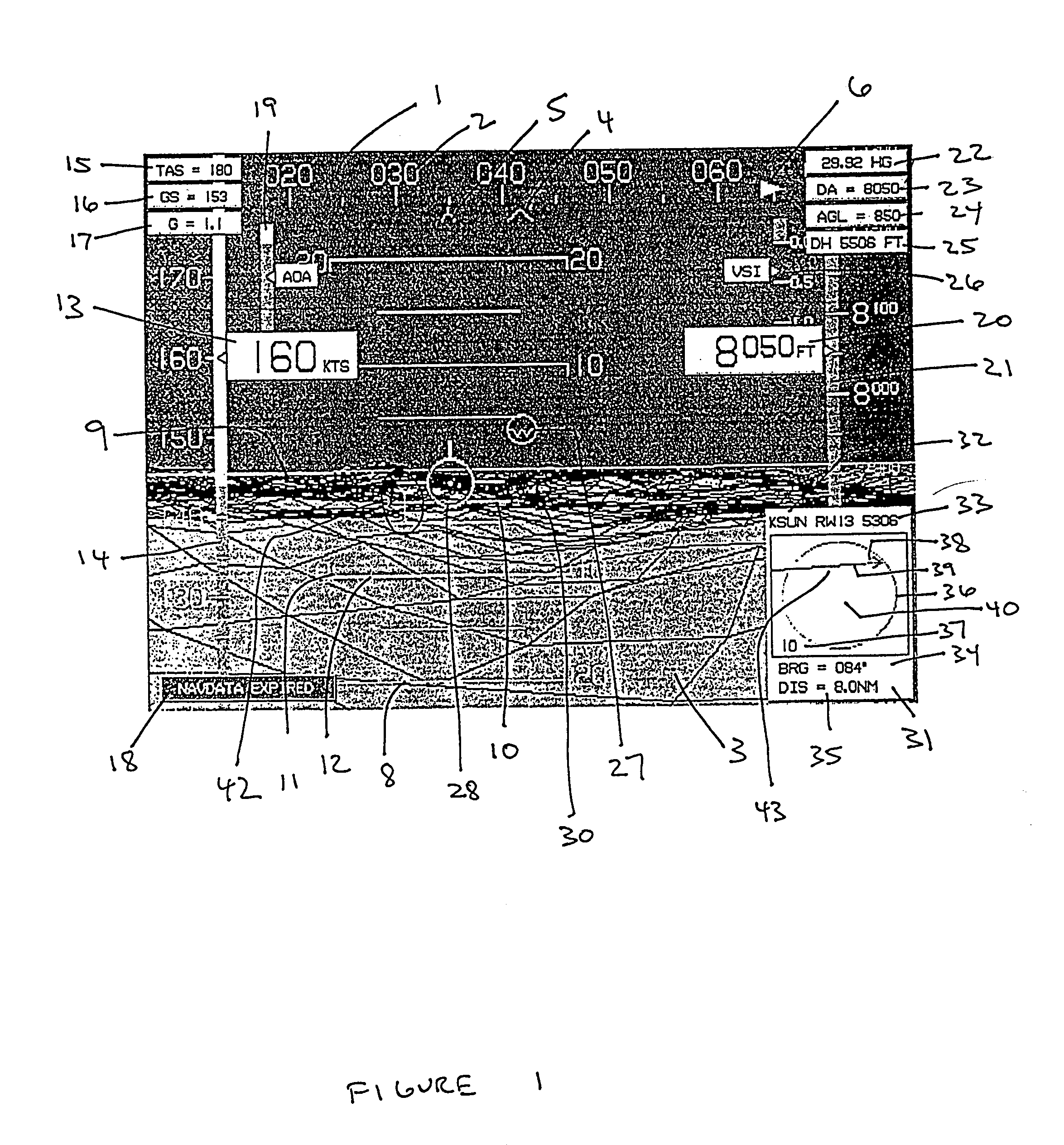
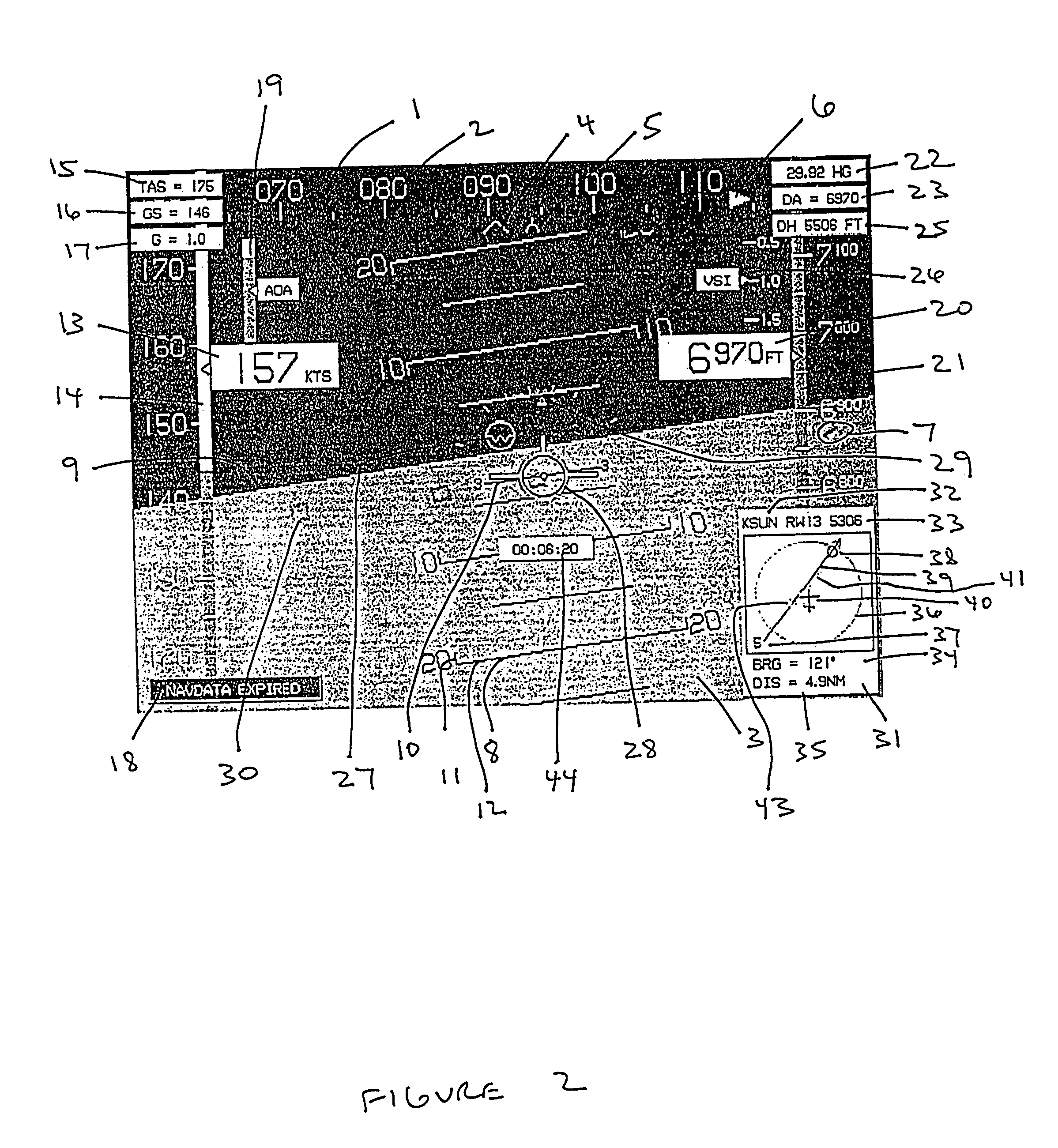
[0023]1. The Primary Flight Display

[0024]Referring now to FIGS. 1 and 2, the primary flight display of the present invention is disclosed. The primary flight display includes a heading scale 1 across the top. The heading scale is preferably aligned with magnetic North although it can also be aligned with true North. The digits 2 of the heading scale are spaced so that, at an aircraft roll angle of zero, the digits conform to the three-dimensional primary flight display background 3. The background 3 is generated from terrain elevation and obstruction elevation data stored in electronic memory. In the preferred embodiment, provision is made for the pilot to be able to selectively enable and disable terrain and obstruction rendering. In some cases, it is preferable to deselect terrain and obstruction rendering to enhance readability of navigation symbology. The heading scale 1 includes a heading carat 4 aligned with the longitudinal axis of the aircraft, and a track pointer 5 aligned ...


PUM


Abstract

The present invention is directed to novel primary flight displays, moving map displays and engine parameter displays for aircraft cockpits. These displays process data gathered from various aircraft sensors and, using an various electronic databases, generate intuitive symbols that aid the pilot. The present invention also uses various novel algorithms that use data gathered from inexpensive sensors to derive parameters normally requiring far more expensive sensors.

Description

[0001]This application is a divisional of U.S. patent application Ser. No. 09 / 540,256 filed Mar. 31, 2000 was abandoned, which in turn claims the benefit of Prov. App. No. 60 / 127,341 filed Apr. 1, 1999.BACKGROUND OF THE INVENTION[0002]1. Field of the Invention[0003]The present invention generally relates to the field of electronic flight instrument displays and, in particular, to primary flight displays, moving map displays, and engine parameter displays presented on electronic screens in aircraft cockpits.[0004]2. Description of the Prior Art[0005]It is well known in the art to provide displays presented on electronic screens in aircraft cockpits. Most modern commercial and military aircraft have several electronic screens capable of presenting: primary flight displays, moving maps or horizontal situation displays, engine parameter displays, and other displays. The present invention is directed to improvements and novel concepts related to primary flight displays, moving maps, and ...

Claims


Application Information

Patent Timeline
Patent Type & Authority Patents(United States)
IPC IPC(8): G01C23/00
CPCG01C23/005
Inventor PRICE, RICARDO A.
Owner CHELTON FLIGHT SYST INC
Why Eureka
Try Eureka