Module type mini BNC connector

a mini-bnc connector and module technology, applied in the direction of coupling device connection, two-part coupling device, electrical apparatus, etc., can solve the problems of shortening the working time changing the electrical performance of the respective terminal, and affecting so as to improve the quality of the signal transmission, reduce the cost of manufacturing, and facilitate manufacturing

Inactive Publication Date: 2005-03-15
INSERT ENTERPRISE
View PDF12 Cites 16 Cited by
  • Summary
  • Abstract
  • Description
  • Claims
  • Application Information

AI Technical Summary

Benefits of technology

A primary object of the present invention is to provide a module type mini BNC connector, which is possible to enha

Problems solved by technology

As the foregoing, the conventional module type mini BNC connector adopts a two piece combined outer casing and although it is easy for the terminals and the insulators to mount in the outer casing, the two piece parts of the outer casing have to be fabricated independently before being joined to each other and more material cost and longer working time are needed.
Further, the front and th

Method used


Image

  • Module type mini BNC connector
  • Module type mini BNC connector
  • Module type mini BNC connector

Examples


first embodiment

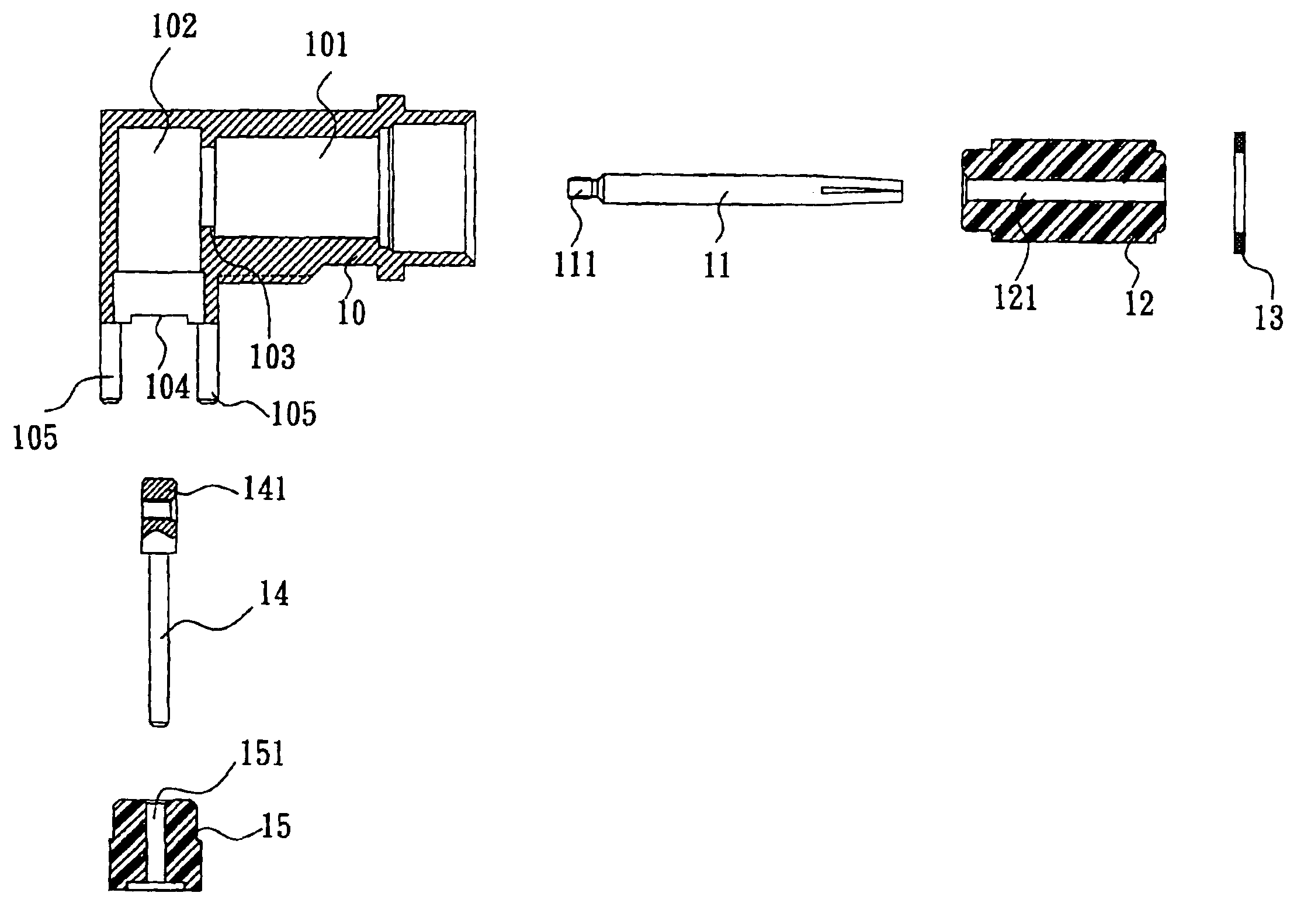
Referring to FIG. 2A, a module type mini BNC connector of the present invention in a first embodiment thereof has a metal outer casing 10 and the metal outer casing 10 further has a locating cylinder 101 and a joining chamber 102 communicating with an inner end of the locating cylinder 101. The locating cylinder 101 at the inner thereof is inserted with a terminal front section 11, a front insulator 12 and a packing ring 13 respectively. The locating cylinder 101 at the inner end thereof provides a rib 103 to fix the insulator 12 in place. The front insulator 12 has an outer diameter slightly smaller than that of the locating cylinder 101 and the front insulator 12 at the upper end thereof is surrounded and fits with the packing ring 13 so that the front insulator 12 can be fixedly attached to the inner side of the locating cylinder 101. The front insulator 12 has a piercing hole 121 to engage with a tail end 111 of the front section 11 so that the front section 11 can be fixedly at...

second embodiment

With reference to FIGS. 3A and 3B again, the terminal 21 in the second embodiment has a front section 211 and a rear section 212 and an annual recess 213 surrounding the terminal 21 between the front section 211 and the rear section 212 to facilitate the bent position being fixed and the rear section 212 being bent 90°.

While the module type mini BNC connector of the preceding embodiment is being assembled, the rear section 212 is slightly bent to pass through a locating cylinder 201 of the outer casing 20 and extend outward the opening 203 of the joining chamber 202 and then is bent 90° at the annular recess 213. Further, the rear insulator 24 at the piercing hole 241 thereof is joined to the rear section 212 of the terminal 21 and inserted into the joining chamber 202 before the opening 203 is closed. Then, the front insulator 22 at the piercing hole 221 thereof is joined to the front section 211 of the terminal 21 and the front insulator 22 is fixed in the locating cylinder 201 wi...


PUM


Abstract

A module type mini BNC connector includes a metal outer casing, a front insulator, a terminal and a rear insulator. The metal outer casing is provided with a locating cylinder and a joining chamber with an opening communicates with the inner side of the locating cylinder. The front insulator is fitted in the locating cylinder with a piercing hole. The terminal has a front section and a rear section with the front section being joined to the piercing hole with a tail end extending to the joining chamber and the rear section being joined to the tail end. The rear insulator with a piercing hole is joined to the rear section of the terminal and is fitted to an inner side of the joining chamber at the opening thereof.

Description

BACKGROUND OF THE INVENTION1. Field of the InventionThe present invention relates to a module type mini BNC connector, and particularly to a mini sized and easily fabricated module type BNC connector.2. Description of Related ArtIn order to enhance signal transmission quality of the BNC connector with metal outer casing, the applicant has filed an invention in Taiwan with Application No. 91206496 and in U.S. with application Ser. No. 10 / 173,462, entitled BNC CONNECTOR WITH ALL METAL OUTER CASING. The prior art basically has a metal cover is joined to an outer casing at the lower end thereof to constitute a space for receiving the BNC connector and the lead wires extending from the rear side of the BNC connector. Hence, the power loss rate of the BNC connector during the signal being transmitted can be reduced and the electromagnetic wave interference generated by the foreign electronic parts can be resisted so as to enhance the quality of the transmitted signal.However, the precedin...

Claims


Application Information

Patent Timeline
IPC IPC(8): H01R13/00H01R13/646H01R43/16H01R13/625
CPCH01R43/16H01R24/50H01R13/625H01R2103/00
Inventor CHEN, SUNG-WENHUANG, TUNG-LIANG
Owner INSERT ENTERPRISE
Why Eureka
Try Eureka