
System for building management of electricity via network control of point-of-use devices

a technology for building management and electricity, applied in the direction of programme control, coupling device connection, instruments, etc., can solve the problems of new plants, not coming on-line quickly enough to deal with the increase in energy demand, waste of commercial and industrial buildings a disproportionate amount of energy, etc., to reduce the consumption of resources being monitored, reduce power consumption, and reduce the effect of investmen

Active Publication Date: 2013-07-18
CORTLAND RES
View PDF10 Cites 70 Cited by
  • Summary
  • Abstract
  • Description
  • Claims
  • Application Information

AI Technical Summary

Benefits of technology

The patent describes a system that collects information from real-time, non-invasive methods using smart outlets. These outlets can integrate various functions such as communication, antennas, and data converters into compact designs. The system has several benefits such as reduced resource consumption, user payback, ease of installation, maintenance, and utilization. It also means lower operating expenses, lower carbon emissions, and higher profits.

Problems solved by technology

And not surprisingly, commercial and industrial buildings waste a disproportionate amount of that energy.
In the US, the average power generating station was built in the 1960s and new plants, due to cost and the permitting process, are not coming on-line rapidly enough to deal with the increased demand for energy.
While these efforts have resulted in substantial energy savings, none focuses upon the final usage endpoint, the electrical outlet or switch.
Computers, printers, copiers, and other devices continue to consume energy even when not in use.
Overnight, weekends and holidays—even in standby, energy is consumed and wasted.
Much like soaring healthcare costs due in part to consumers not shopping for the least expensive care, individuals have little incentive to reduce energy usage since the attendant savings do not accrue to the individual.

Method used


Image

  • System for building management of electricity via network control of point-of-use devices
  • System for building management of electricity via network control of point-of-use devices
  • System for building management of electricity via network control of point-of-use devices

Examples


Embodiment Construction

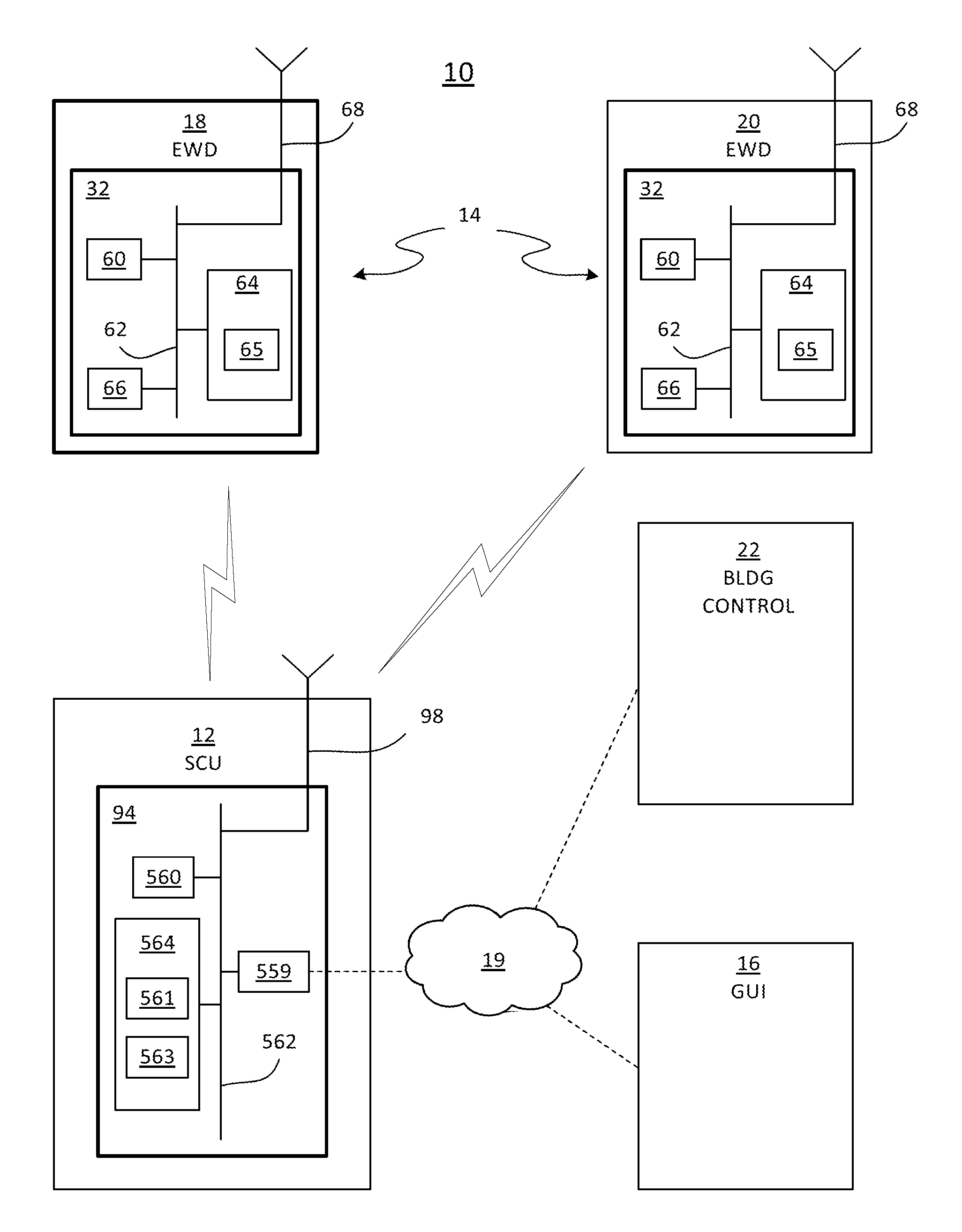
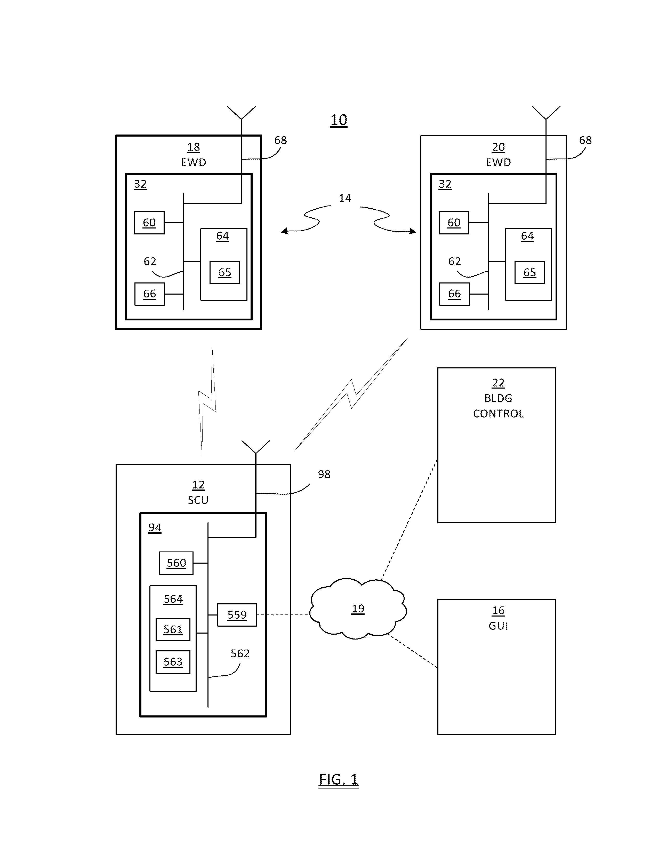
[0025]Referring to FIG. 1, block diagram for a point-of-use, network-controlled system 10 for monitoring and controlling electricity usage in a building is shown. The system 10 includes a system control unit 12, one or more enhanced wiring devices 14 in wireless communication with the system control unit, and a user interface 16 in communication with the system control unit. The enhanced wiring devices 14 are hard-wired to a building's wiring system (not shown), and replace or supplant conventional receptacle boxes and switches. As illustrated, embodiments of the enhanced wiring device 14 may include a wall-mounted outlet 18 or a wall-mounted switch 20. Each enhanced wiring device 14 includes one or more sensors to monitor stimulus parameters in the room, such as temperature, presence of occupants, power consumption of appliances connected to the electrical load, and current draw of the load, for example.

[0026]The user interface 16 (or user platform) may be embodied as a computer su...


PUM


Abstract

A system for monitoring and controlling electricity usage in a building includes a system control unit and an enhanced wiring device in wireless communication with the system control unit. The enhanced wiring device is hard-wired into the building electrical infrastructure, and is selected from the group consisting of an electrical outlet receptacle and an electrical power switch. The enhanced wiring device further includes a sensor for monitoring a stimulus parameter in a room of the building, a processor, at least one memory coupled to the processor, and program instructions stored on the at least one memory for execution by the processor to evaluate and communicate data from the sensor. The enhanced wiring device further includes an antenna for transmitting the sensor data to the system control unit, and a user interface connected to the system control unit adapted to configure and monitor data from the enhanced wiring device.

Description

CROSS REFERENCE TO RELATED APPLICATION[0001]Reference is made to and this application claims priority from and the benefit of U.S. Provisional Application Ser. No. 61 / 583,800, filed Jan. 6, 2012, entitled “SYSTEM FOR BUILDING MANAGEMENT OF ELECTRICITY VIA NETWORK CONTROL OF POINT-OF-USE DEVICES” which application is incorporated herein in its entirety by reference.FIELD OF THE INVENTION[0002]The present invention relates to systems for control of electricity usage; more particularly, to such systems that include point-of-use devices; and most particularly, to a system incorporating a plurality of “smart” point-of-use electrical receptacles and switches, a system control unit, and a graphical user interface.BACKGROUND OF THE INVENTION[0003]Energy conservation is one of the most important investments that existing business owners can employ in their physical infrastructure to increase profits while helping the environment. The “low-hanging fruit” in building efficiency investments has...

Claims


Application Information

Patent Timeline
Patent Type & Authority Applications(United States)
IPC IPC(8): G05B13/02
CPCG05B15/02G05B13/02G05B2219/2642H01R13/4534
Inventor MCMAHON, STEPHEN
Owner CORTLAND RES
Learn More