Wireless communication systems

a communication system and wireless technology, applied in power management, sustainable buildings, high-level techniques, etc., to achieve the effect of reducing the electric power required and simplifying the power supply configuration and power supply control

Inactive Publication Date: 2006-06-15
HITACHI LTD
View PDF13 Cites 62 Cited by
  • Summary
  • Abstract
  • Description
  • Claims
  • Application Information

AI Technical Summary

Benefits of technology

[0023] According to the present invention, if a power supply is provided for the power supply system of the radio frequency analog front end part, the signal strength of a received signal can be measured, and power supply configuration and power supply control can be simplified.
[0024] Since the electric power consumption particularly in nearby wireless communications generally becomes larger the case of reception than in the case of transmission, the effect of reducing the electric power required for reception for carrier sensing is big.

Problems solved by technology

In particular, in case the terminal is not used in a state where permanent communication with the base station is possible, there is a need for the terminal to continue standby operation, and the electric power consumption during this standby operation exerts a great influence on the operating life of the terminal.

Method used


Image

  • Wireless communication systems
  • Wireless communication systems
  • Wireless communication systems

Examples


first embodiment

1. First Embodiment

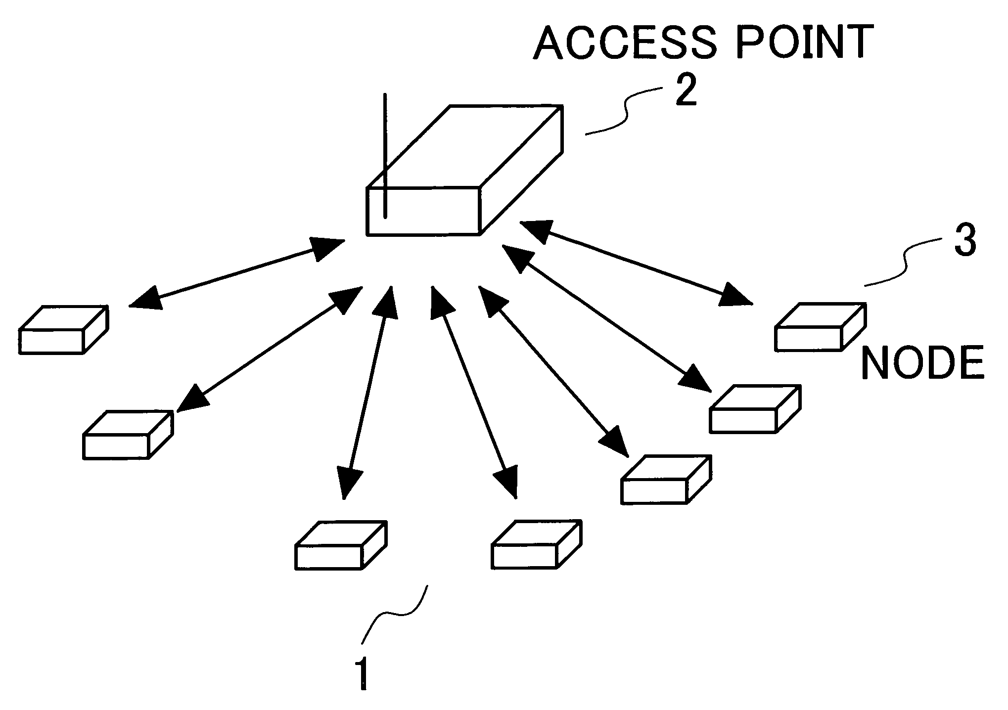
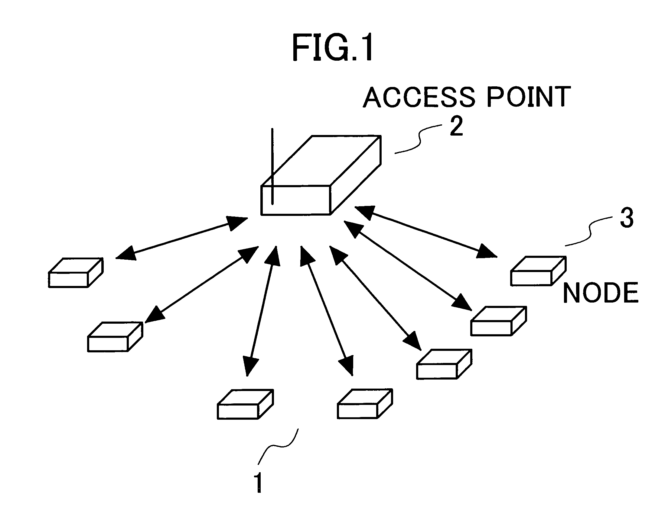
[0037] In the following, the embodiments of the present invention will be explained using the figures. The configuration of the whole system is similar to that in FIG. 1, and the configurations of the terminal and the base station are as shown in FIG. 5 and FIG. 6, respectively.

[0038]FIG. 5 is a diagram showing the details of the wireless part of a terminal according to the present invention. The operation of transmitting and receiving is similar to that of the terminal shown in FIG. 3. The points of difference are the points of providing a power supply management part 100 and dividing the internal parts of the wireless part into circuit blocks 101 to 105 so as to be able to switch the supply destinations of the power supply depending on the operating conditions. By providing a power supply only to those circuit blocks, from among circuit blocks 101 to 105, which are minimally required in the operation of transmission, reception, and carrier sensing, respectively...

second embodiment

2. Second Embodiment

[0048] In the following, an explanation will be given, using the drawings, of another embodiment of the present invention. FIG. 10 is a diagram showing another example of an operating sequence of the terminal. FIG. 11 is a diagram showing another example of a procedure for wireless communication between a base station and a terminal. It is considered that one frequency is used in the present embodiment, base station 2 transmits the beacon signal periodically (P20), and that terminal 3 performs carrier sensing of the beacon signal (P20) of base station 2 and measures the signal strength of the received signal.

[0049] By taking the beacon signal (P20) transmitted by base station 2 and the timing of the carrier sensing of terminal 3 to have different periods, it is possible to capture the beacon signal (P20) of the base station by performing carrier sensing a number of times, in case base station 2 is present in the range within which communication with terminal 3 i...


PUM


Abstract

In a wireless communication system having a base station and a terminal, it is important to extend the operating life of the terminal in the case of using a battery as the power supply of the terminal. Particularly in the case where a state in which a base station is not present in the range within which the terminal can communicate lasts long, the reduction of the electric power consumption during the standby of the terminal becomes an issue. The terminal monitors the received signal power strength of a signal transmitted by the base station. When the power strength exceeds a prescribed value, it is considered that the base station is present and the base station performs operations for carrying out communication with the base station.

Description

INCORPORATION BY REFERENCE [0001] The present application claims priority from Japanese application JP 2004-359,314 filed on Dec. 13, 2004, the content of which is hereby incorporated by reference into this application. BACKGROUND OF THE INVENTION [0002] 1. Field of the Invention [0003] The present invention is an invention which is concerned with a wireless communication system comprising a base station and a terminal and which pertains in particular to the configuration, and the control method therefor, of the wireless part of a terminal for implementing the attainment of power savings during the standby of the terminal. [0004] 2. Description of the Related Art [0005] When it comes to conventional wireless communication systems, there exist e.g. systems such as sensor nets and RF-ID (Radio Frequency Identification) tags (refer to: “Sensor Networks: Evolution, Opportunities, and Challenges”, Proceedings of the IEEE, Vol. 91, No. 8 (August 2003), pp. 1247-1256). Below, an explanatio...

Claims


Application Information

Patent Timeline
Patent Type & Authority Applications(United States)
IPC IPC(8): H04B7/00
CPCH04W52/0245H04W52/283H04W52/287Y02B60/50Y02D30/70
Inventor SHIDA, MASAAKISUZUKI, KEIKUWAHARA, MIKIO
Owner HITACHI LTD
Why Eureka
Try Eureka