
Stacking frame structure of superwide container

A container and frame structure technology, applied in the field of stacking frame structure, can solve the problems of container cargo space occupation, insufficient strength, unsafe use, etc., and achieve the effect of convenient use

Inactive Publication Date: 2007-05-02
CHINA INTERNATIONAL MARINE CONTAINERS (GROUP) CO LTD
View PDF0 Cites 2 Cited by
  • Summary
  • Abstract
  • Description
  • Claims
  • Application Information

AI Technical Summary

Problems solved by technology

As shown in Figure 6, a stacking frame 2 that is currently in use is arranged at a position close to the end of the ultra-wide container body, and is arranged on two top corner fittings 20 at the top corners of the stacking frame 2. There are two pairs of lifting holes 201 and 202, wherein the center distance between the lifting holes 202 on the inside of the box body is 2260mm, and the center distance between the lifting holes 201 on the outside of the box body is 2448mm, which makes the stacking frame 2. The center-to-center distances of the top holes are 2260mm and 2448mm respectively, so that the ultra-wide container can meet the hoisting requirements of both international transport and inland transport in North America; The top corner fittings on the top of the frame are large in size, occupying too much cargo space of the container, and according to the container ISO standard, the width of the connecting part of the two lifting holes on the same corner fitting is only 30.5mm, and the height of the connecting part is 28.5mm; according to this calculation, the strength of the connecting part of the two lifting holes is not enough, it is easy to deform, the stress is too large, and it is unsafe to use. Therefore, the structure of the stacking frame 2 shown in Figure 6 that has been used at present needs to be further improved

Method used


Image

  • Stacking frame structure of superwide container
  • Stacking frame structure of superwide container
  • Stacking frame structure of superwide container

Examples


Embodiment 1

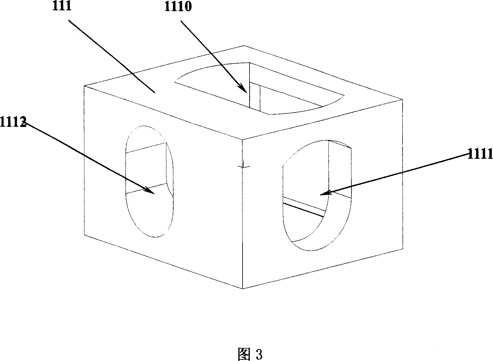
[0029] As shown in Figure 7, a stacking frame structure 31 of an ultra-wide container includes corner posts 310 on both sides, a top corner piece 311 arranged at the top of the corner post 310, a bottom corner piece 312 at the bottom of the corner post 310, and a horizontally connected The upper beam 313 between the two top corner pieces 311 and the lower beam 314 between the two bottom corner pieces 312, the top corner pieces at both ends of the top corner of the stacking frame are provided with three lifting holes, two of which are parallel to each other. Adjacent to the top of one end corner fitting 311 at the top corner of the stacking frame, there are respectively inner holes 3112 and outer holes 3111, and the third lifting hole 3110 is arranged at the other end corner fitting 311' at the top corner of the stacking frame. At the top, the distance between the center of the inner hole 3112 on the corner fitting 310 and the center of the lifting hole 3110 of the corner fittin...

Embodiment 2

[0032] As shown in Figures 9 and 10, the double-hole corner fitting used in this embodiment adopts the earliest design of British REYNARD INTERMODAL ENGINEERING. When the turnlock goes deep into the inner hole 3112, it will force the flexible diaphragm 3113 to deflect, providing space for the deep turnlock ; When the twist lock withdraws, the flexible diaphragm 3113 returns to its original shape, so that the thickness of the corner piece can be reduced a lot, so as to achieve the purpose of increasing the loading space as much as possible.

Embodiment 3

[0034]As shown in Figure 11, the inner and outer holes 3112, 3111 are respectively located on two separate corner fittings 311" and 311, so that the most common corner fittings can be used respectively, and they can be combined according to different positions to have a larger Flexibility saves costs.


PUM

PropertyMeasurementUnit
Center distanceaaaaaaaaaa

Abstract

A stacking frame structure for the ultra-wide container has the corner posts at both sides, the transverse top beams between the tops of said corner posts, and 3 lifting holes on its top corner parts. Said lifting holes are such distributed that two of them are made on the top corner parts at one end and one hole is made on the top corner part at another end in order to meet the lifting standard of ISO.

Description

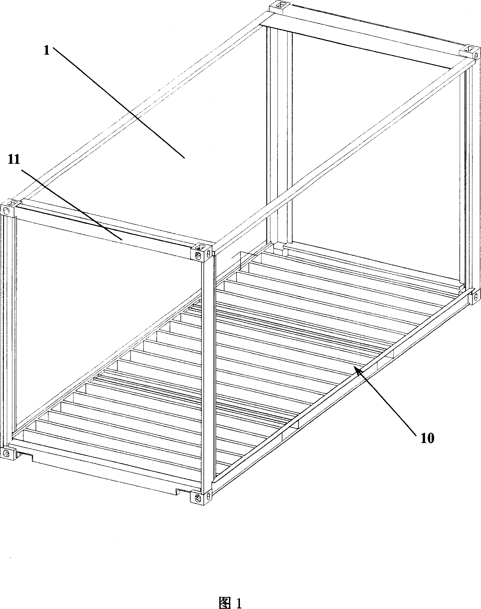
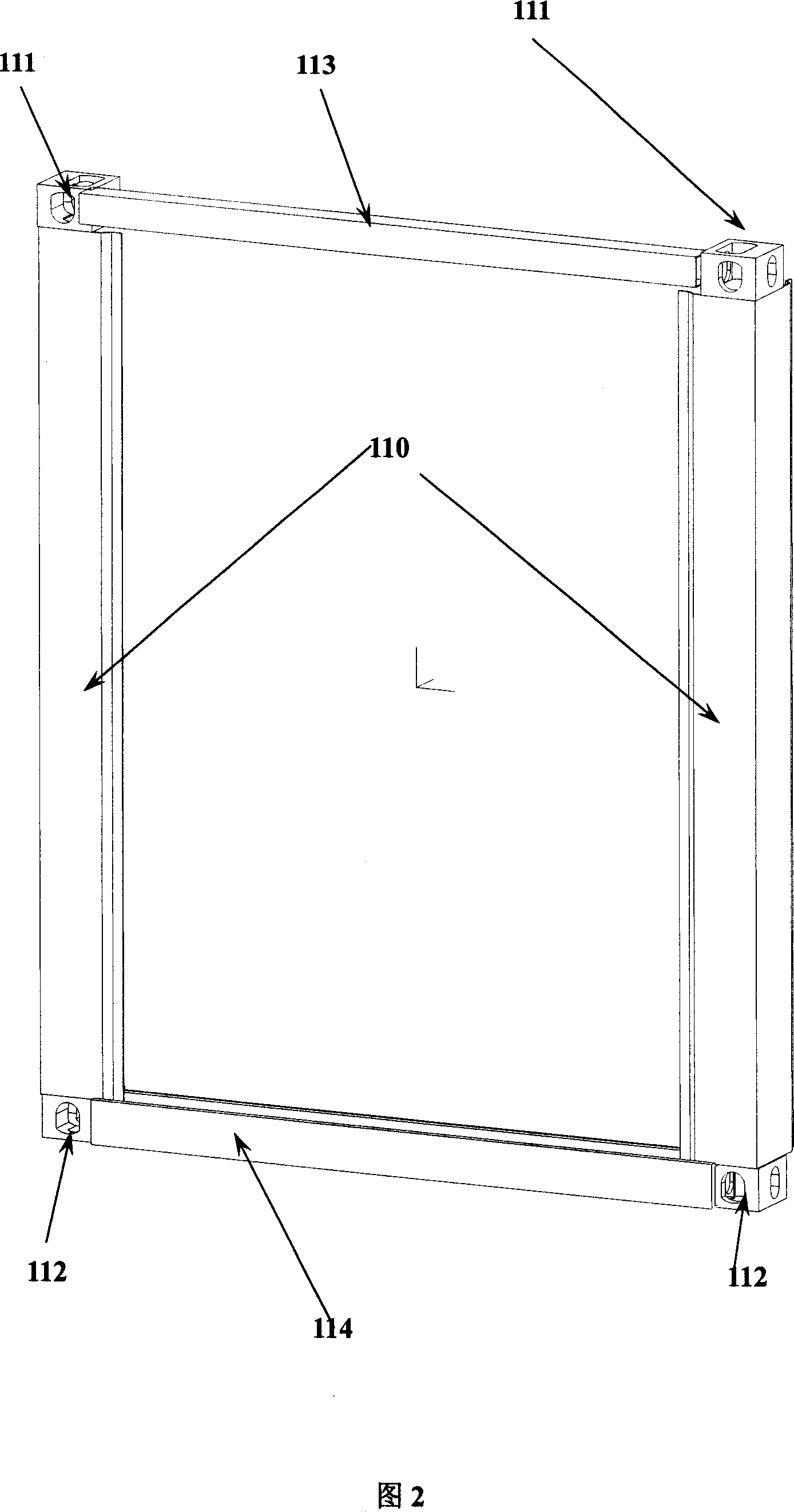
technical field [0001] The invention relates to a part of a large rigid container, in particular to a stacking frame structure of an ultra-wide container. Background technique [0002] As a means of freight transportation, containers have developed into an international standard means of multimodal transport in the 1960s. As shown in Figure 1, a standard container 1 includes an underframe 10 for loading and stacking frames 11 positioned at both ends of the underframe 10, and the external length, width, and height dimensions of the container 1 meet the requirements of the container ISO standard, wherein The width is generally 2438mm (8 feet); as shown in Figure 2, in order to facilitate the hoisting and stacking of the container 1 and the needs of positioning connection, box protection, rigidity and strength during transportation, the stacking frame 11 generally includes a The corner posts 110 on both sides, the top corner fittings 111 arranged at the top of the corner posts...

Claims


Application Information

Patent Timeline
IPC IPC(8): B65D90/20B65D90/00
Inventor 姚谷
Owner CHINA INTERNATIONAL MARINE CONTAINERS (GROUP) CO LTD
Learn More