
Correction method for head position of part installation device and nominal nozzle

A technology of installation device and calibration method, applied in the direction of electrical components, electrical components, etc., can solve problems such as complicated steps, inability to detect accurate heads, and difficulty in accurately identifying nozzles

Inactive Publication Date: 2010-06-23
JUKI CORP
View PDF5 Cites 0 Cited by
  • Summary
  • Abstract
  • Description
  • Claims
  • Application Information

AI Technical Summary

Problems solved by technology

[0008] However, in the method of correcting the head position of the component mounting apparatus in the above-mentioned Patent Document 1, there are very many types of positional relationships to be considered, and any positional relationship must be judged by observing the time-varying operation. As a result of the correction amount, two sets of information of various types are required both before operation and at the time of judgment, and there is a problem that the procedure for judgment is complicated
[0009] In addition, when observing the nozzle of the head with a camera for chip recognition, it is extremely difficult to actually accurately identify the center of the nozzle. From this point of view, it cannot be said that the accurate head (axis center) can be detected. Location

Method used


Image

  • Correction method for head position of part installation device and nominal nozzle
  • Correction method for head position of part installation device and nominal nozzle
  • Correction method for head position of part installation device and nominal nozzle

Examples


Embodiment Construction

[0019] An example of an embodiment of the present invention will be described in detail below with reference to the drawings.

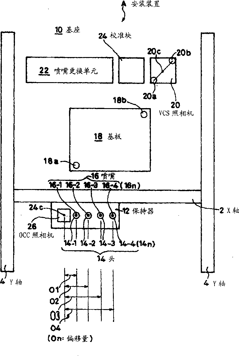
[0020] Such as figure 2 As shown, the electronic component mounting device A to which the present invention is applied has a so-called gantry type XY driving mechanism, and the XY driving mechanism has an X axis 2 and a Y axis 4, and a holder (holding Frame) 12 can move in the X-Y direction. Heads 14 (14-1, ... 14-4) are installed on the holder 12, and nozzles 16 (16-1, ... 16-4) attached to the heads 14 are used to absorb components (not shown). The components are arranged at predetermined positions on the substrate 18 placed above the base 10 . In this embodiment, four heads 14 - 1 to 14 - 4 are attached to one holder 12 . For convenience, the head to be calibrated is denoted by 14n, and the nozzle is denoted by 16n.

[0021] On the base 10 of the mounting apparatus A, a VCS camera (camera for chip identification: first camera) 20 for detecting...


PUM


Abstract

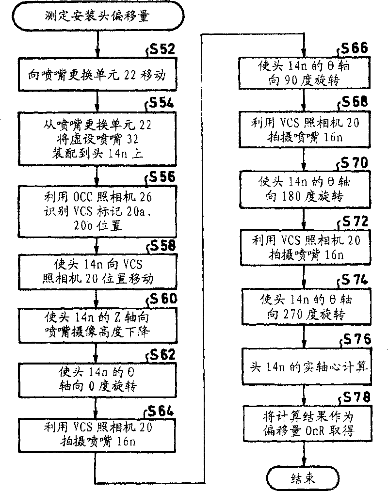
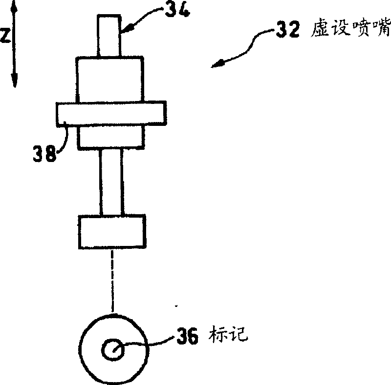
The present invention provides a correction method for head position of a part installation device and a nominal nozzle, wherein, the real offset between the camera for substrate identifying and the head position can be idenfified accurately and also an appropriate correction can be performed through simple steps. A nominal nozzle is installed on the head (14n), and the position of a VCS camera (the first camera) (20) at the substrate (10) side can be identified by an OCC camera (the second camera)(26) of a holding device (12) which is installed with a head (14n). Then, the head (14n) is moved to the identified position of the VCS camera (20) according to the offset (On) on design between the OCC camera (26) and the head (14n). The position sign (36) of the nominal nozzle (32) which has been moved is shot by the VCS camera (20), thus, the offset (OnR) of the moved head from the center of the VCS camera (20) is calculated as an offset correction value.

Description

technical field [0001] The present invention relates to a method of correcting the head position of a component mounting device and a dummy nozzle suitable for use in the correction. Background technique [0002] For example, Patent Document 1 discloses a component mounting apparatus for mounting electronic components such as ICs, LSIs, flip chips, resistor chips, and chip capacitors at predetermined positions on a substrate. This component mounting apparatus has a head having a nozzle for vacuum-adsorbing these components, and the direction of the X-Y direction (horizontal driving) and the Z-axis direction (vertical driving) of the head (specifically, a holder for holding the head) are combined. Combination of movement and the head's own rotation around the Z axis (theta drive), and the parts supplied to the parts feeder (partsfeeder) are mounted on the substrate, [0003] In such a component mounting apparatus, if the position of the nozzle on the X-Y plane recognized by ...

Claims


Application Information

Patent Timeline
Patent Type & Authority Patents(China)
IPC IPC(8): H05K13/04H05K13/08
Inventor 粟野元一郎
Owner JUKI CORP
Learn More