
Pincer nail correction instrument

A technique for appliances and nail rolls, which can be used in medical science and other directions to solve problems such as falling off of correction appliances

Active Publication Date: 2015-12-30
SHIKAHAMA
View PDF6 Cites 0 Cited by
  • Summary
  • Abstract
  • Description
  • Claims
  • Application Information

AI Technical Summary

Problems solved by technology

[0004] But these methods in the past all directly act correcting force to nail by the tightening of threaded unit, and, when under the effect of this correcting force, curly nail is corrected to some extent, the correcting appliance will be dislodged from the nail. fall off
And, because the distance between the hooks on the left and right is only variable in a certain range in the structure of Patent Document 1, but not variable in Patent Document 2, it is difficult to use a single orthodontic appliance for these conventional methods. Correction of nails with different dimensions in the left and right directions of the nail, namely the size of the nail, the thickness of the nail, and the degree of deformation of the nail

Method used


Image

  • Pincer nail correction instrument
  • Pincer nail correction instrument
  • Pincer nail correction instrument

Examples


Embodiment Construction

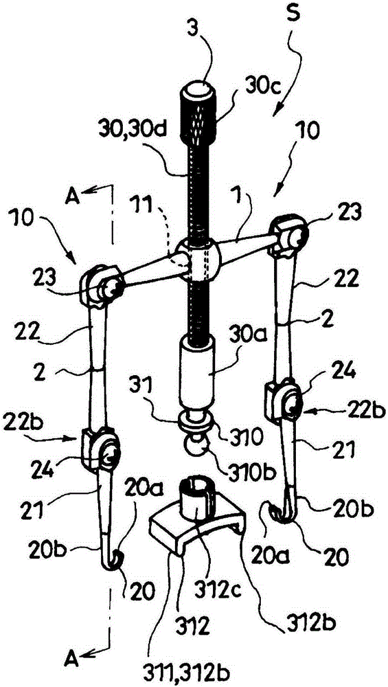
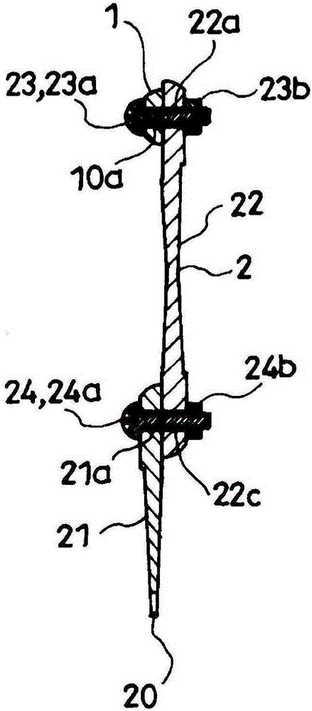
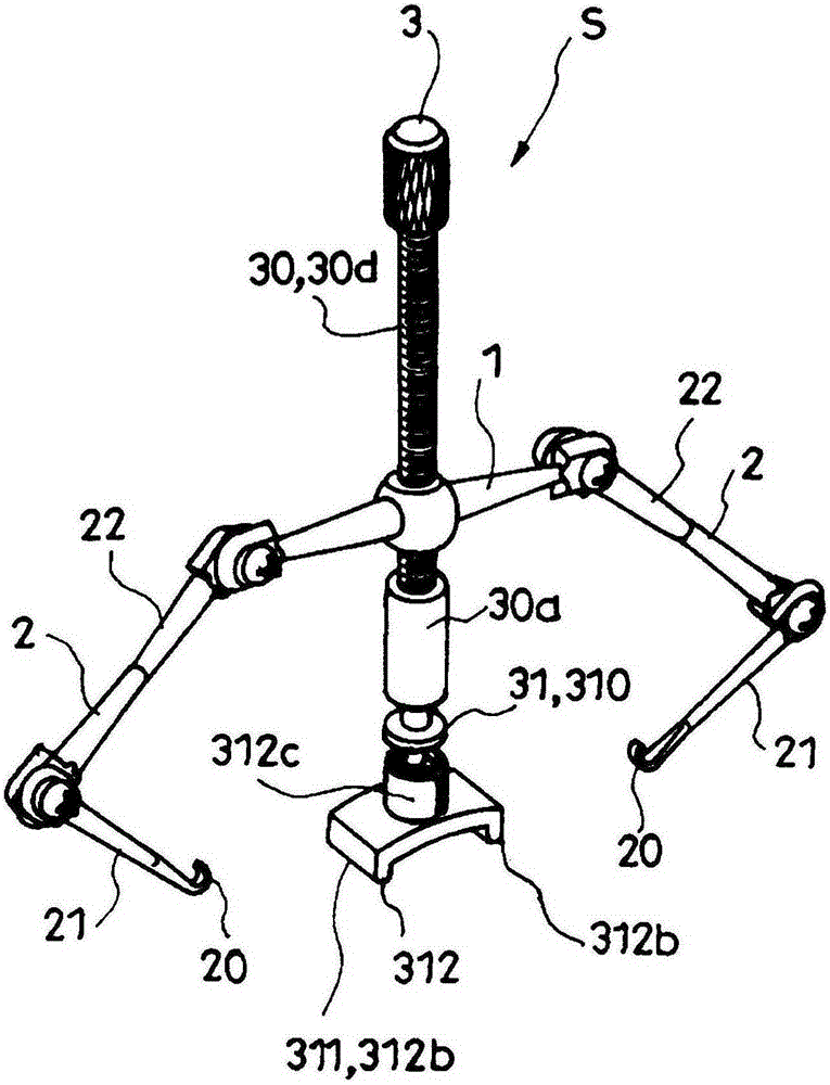
[0027] Below, according to Figure 1 to Figure 7 Typical embodiments of the present invention will be described. The correcting tool S of the present embodiment is attached to a nail N exhibiting curly nails, and is used to correct the nail N to a normal state.

[0028] The orthotic tool S of this embodiment has a base 1 , a left arm 2 , a right arm 2 , and a fulcrum member 3 . The orthodontic appliance S is typically made of metal and synthetic resin. In the illustrated example, a contact portion structure 312 included in the movable body 31 described later is made of synthetic resin, and other members are made of metal.

[0029] The base body 1 has the rotation assembly part 10 of the left arm 2 at its left end part, has the rotation assembly part 10 of the right arm 2 at its right end part, and has an internal thread hole penetrating in the vertical direction at the middle position in the left-right direction. 11. In the illustrated example, the substrate 1 is formed by...


PUM


Abstract

An objective of the present invention is to provide a correction instrument which is mountable without imparting excess force to a nail, and which is appropriately usable for respective correction of nails with different measurements. Provided is a pincer nail correction instrument, comprising: a left-side arm and a right-side arm, further comprising hook parts upon free ends thereof onto the lateral edge parts of a nail; and a fulcrum member between the left-side arm and the right-side arm with lower end parts as contact parts with respect to the nail. The fulcrum member further comprises: an axle which is combined to be vertically threadably extendable and retractable with respect to a base; a movable body which is vertically movably combined with the axle and which disposes the contact parts below the axle; and an impelling member which is interposed between the movable body and the axle with respect to the movable body. The contact member extends to the left and right, and further comprises protrusion parts respectively on the left end and the right end. The contact member makes contact with the nail via the protrusion parts, and does not make contact with the nail between the left and right protrusion parts.

Description

technical field [0001] The present invention relates to a correcting tool mounted on a pincernail to correct the nail to a normal state. Background technique [0002] There are surgery-based treatment and correction-based treatment in the treatment of curly nails, but correction-based treatment has become the mainstream in recent years. [0003] As a correction tool for such a correction, there are products in which hooks hooked to the side edges of the nails are arranged on the left and right sides of the base plate, and the vertical distance between the base plate and the hooks is variable by a screw unit. (Refer to Patent Documents 1 and 2) [0004] But these methods in the past all directly act correcting force to nail by the tightening of threaded unit, and, when under the effect of this correcting force, curly nail is corrected to some extent, the correcting appliance will be dislodged from the nail. fall off. And, because the distance between the hooks on the left ...

Claims


Application Information

Patent Timeline
Patent Type & Authority Applications(China)
IPC IPC(8): A61F5/11
CPCA61F5/013A61F5/11
Inventor 鹿浜茂
Owner SHIKAHAMA
Learn More