Misfire detecting device of internal combustion engine

A detection device and internal combustion engine technology, applied in the direction of mechanical equipment, engine control, machine/engine, etc., can solve problems such as many man-hours, inability to accurately determine cylinder misfire, and complicated misfire determination processing, etc., to achieve accurate misfire determination and versatility high effect

Inactive Publication Date: 2010-01-13
HONDA MOTOR CO LTD
View PDF5 Cites 0 Cited by
  • Summary
  • Abstract
  • Description
  • Claims
  • Application Information

AI Technical Summary

Problems solved by technology

Therefore, there is a problem that the misfire determination process is complicated
[0005] Furthermore, it may not be possible to accurately determine in which cylinder a misfire has occurred, and there is a problem that the processing content changes with the number of cylinders of the internal combustion engine, or the setting of the determination threshold requires many man-hours.

Method used


Image

  • Misfire detecting device of internal combustion engine
  • Misfire detecting device of internal combustion engine
  • Misfire detecting device of internal combustion engine

Examples


no. 1 approach

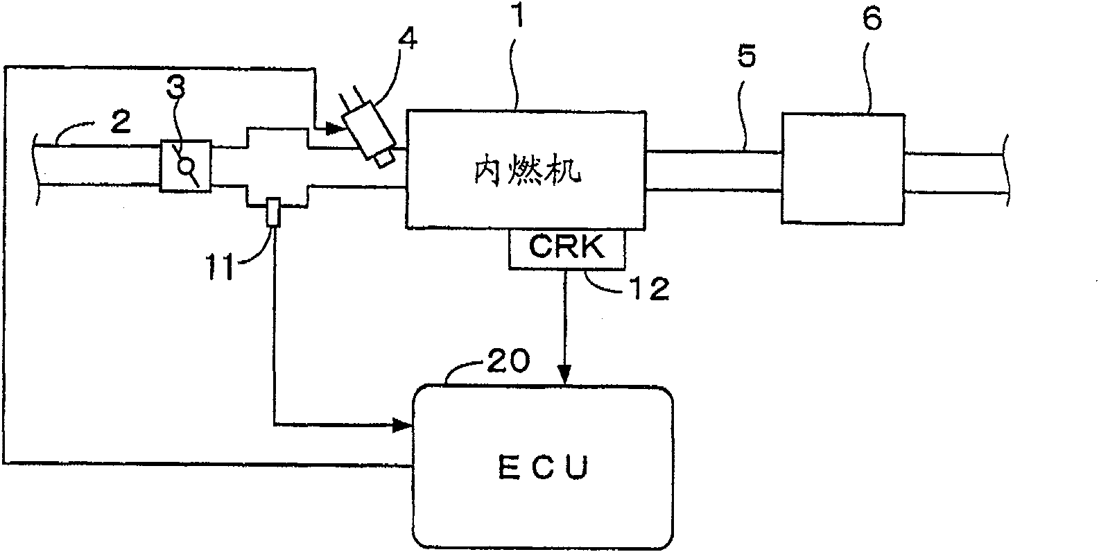
[0045] figure 1 It is a diagram showing the configuration of an internal combustion engine and its control device according to an embodiment of the present invention. An internal combustion engine (hereinafter referred to as “engine”) 1 has, for example, six cylinders, and includes an intake pipe 2 and an exhaust pipe 5 . A throttle valve 3 is provided in the intake manifold 2 . Also, a catalytic converter 6 for purifying exhaust gas is provided in the exhaust pipe 5 .

[0046] Each cylinder is provided with a fuel injection valve 4, which is arranged between the engine 1 and the throttle valve 3 and is located on the slightly upstream side of the intake valve not shown in the intake pipe 2. The pump is connected and electrically connected to an electronic control unit (hereinafter referred to as “ECU”) 20 , and the opening timing of fuel injection valve 4 is controlled by a control signal from ECU 20 .

[0047] Immediately downstream of the throttle valve 3 is provided an ...

no. 2 Embodiment approach

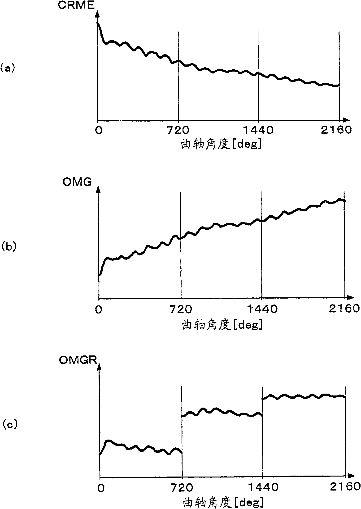
[0109]In the above-mentioned embodiment, the time parameter CRME is converted into the rotational speed OMG, and the misfire determination is performed using the rotational speed OMG as the speed parameter, but in this embodiment, the misfire determination is performed using the time parameter CRME as the speed parameter. In addition, it is the same as that of the first embodiment except for the points described below.

[0110] Figure 10 It is a flowchart of the misfire determination process using the time parameter CRME as the speed parameter.

[0111] In step S32, the 720-degree filtering process is performed by the following formula (21), and the post-filtering time parameter CRMER(i) is calculated.

[0112] CRMER(i) = CRME(i)

[0113] -(CRME(0)-CRME(ND))×Dθ×i / 4π

[0114] (twenty one)

[0115] In step S33, the relative time parameter CRMEREF(i) is calculated by the following formula (22).

[0116] CRMEREF(i)=CRMER((k-1)NTDC)-C...


PUM


Abstract

To provide a misfire detecting device of an internal combustion engine which can accurately determine the misfire of each cylinder by relatively easy computing, and which has high general versatility. A deviation between a standard rotation speed OMGR ((k-1)NTDC) and a rotation speed parameter (OMGR(i)) is calculated as a relative rotation speed OMGREF(i) (S12, S13). The standard rotation speed OMGR is detected near a compression top dead center of each cylinder, and the rotation speed parameter (OMGR(i)) is detected on a predetermined crank angle. Then an inertial force rotation speed OMGI(k) is calculated which indicates the speed component caused by the inertial force of the reciprocating motion part or the like of the internal combustion engine (S14). The relative rotation speed OMGREF(i) is modified by this, and the modified relative rotation speed OMGREFM(i) is calculated (S15). By the summation of the modified relative rotation speed OMGREFM(i), a determination parameter MFJUD(k) is calculated (S16), and misfire determination is made based on the judgement parameter MFJUD (S17).

Description

technical field [0001] The invention relates to a misfire detection device of an internal combustion engine, in particular to a device for judging whether there is misfire according to a rotational speed parameter corresponding to the rotational speed of the internal combustion engine. Background technique [0002] Patent Document 1 discloses a method in which a characteristic signal q(n) is formed based on a segmental time required for rotation of a predetermined crank angle, and the presence or absence of misfire is determined based on the characteristic signal q(n). The characteristic signal q(n) is a signal indicating the segment time, and is converted into a signal shown as a point on the complex plane, and the presence or absence of a misfire is determined based on the magnitude and phase of the characteristic signal q(n). [0003] Patent Document 1: Japanese Patent Application Laid-Open No. 9-119338 [0004] In the above-mentioned conventional methods, a band-pass fi...

Claims


Application Information

Patent Timeline
Patent Type & Authority Patents(China)
IPC IPC(8): F02D45/00
Inventor 塚本宗纪四竈真人
Owner HONDA MOTOR CO LTD
Why Eureka
Try Eureka