Spin lock and key thereof

A screw and key technology, applied in the field of marble locks and keys, can solve the problems of single slot structure, unsatisfactory safety and anti-theft performance, etc., and achieve the effect of increasing safety and confidentiality performance.

Inactive Publication Date: 2007-05-16
中山市明丰五金制品有限公司
View PDF0 Cites 9 Cited by
  • Summary
  • Abstract
  • Description
  • Claims
  • Application Information

AI Technical Summary

Problems solved by technology

However, the lock keyhole of domestic and foreign tumbler locks and the matching key teeth and grooves have a single structure, and it is easy to unl

Method used


Image

  • Spin lock and key thereof
  • Spin lock and key thereof

Examples


Embodiment Construction

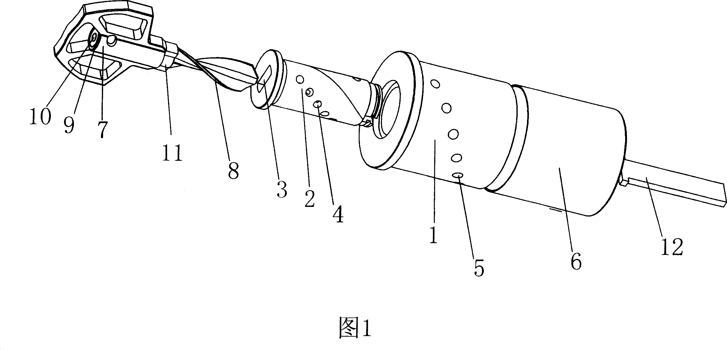
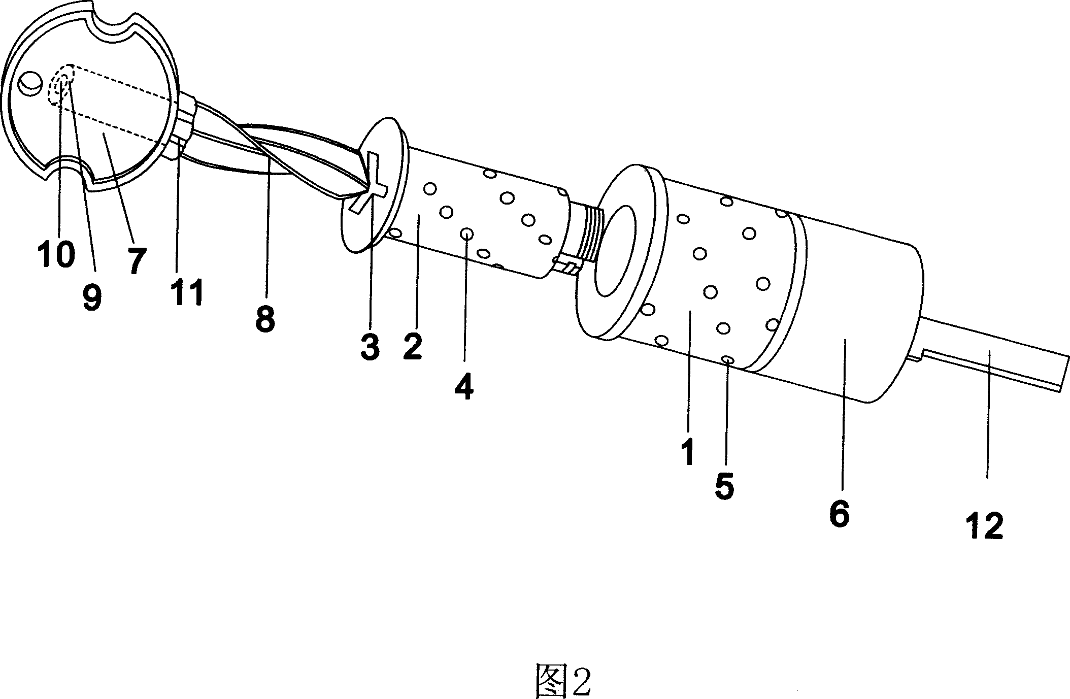
[0018] Referring to Fig. 1, Fig. 1 is a structural schematic diagram of a first embodiment of a screw lock and its key, as shown in the figure, the screw lock includes a lock body 1, and a cover 6 is installed on the lock body 1, and is installed in the lock body 1 There is a lock cylinder 2, one end of the lock cylinder 2 can be installed with a lock ruler 12, and a spiral keyhole 3 is arranged in the lock cylinder 2, the spiral keyhole 3 is a two-spiral structure, and the spiral keyhole 3 The helix angle is best set to 180-270°.

[0019] The lock cylinder 2 is provided with pinball holes 4 arranged in a spiral shape, the pinball holes 4 communicate with the bottom of the spiral keyhole 3, and the lock body 1 is provided with bead holes 5 corresponding to the pinball holes 4 .

[0020] As shown in the figure, in order to cooperate with the opening of the above-mentioned screw lock, the present invention discloses a key, which includes a key handle 7 . A helical tooth portio...


PUM

PropertyMeasurementUnit
Helix angleaaaaaaaaaa

Abstract

The spiral lock comprises a body and a core within the body, featuring on the spiral key hole in the core and the spirally arranged hoodle holes on the said core, with the bottom of the spiral key hole connected with the hoodle holes which correspond to the holes on the body. A key, with its handle equipped with spiral teeth matched with the spiral key hole, is meant to match with the said spiral lock. The invention adds security with the effects of anti-poking and anti-vibration.

Description

technical field [0001] The invention relates to a tumbler lock and a key thereof. Background technique [0002] Looking at all the locks currently on the market, whether it is a high-tech product integrating sound, light, machinery and electricity, or the most common lock, the most popular and most used mechanical lock is the tumbler lock. And the lock keyhole of domestic and international tumbler lock and the key tooth that cooperates with it, groove structure are single, easily unlock by technical methods such as stirring or vibrating pin, therefore, the safety and antitheft performance of these locksets are not ideal enough. Contents of the invention [0003] The first object of the present invention is to provide a screw lock that can achieve anti-dialing, anti-vibration and safety. [0004] Another object of the present invention is to provide a key compatible with the above-mentioned twist lock. [0005] The technical solution adopted by the present invention to so...

Claims


Application Information

Patent Timeline
IPC IPC(8): E05B35/06E05B19/06E05B27/02
Inventor 李明
Owner 中山市明丰五金制品有限公司
Why Eureka
Try Eureka