Supercharge Your Innovation With Domain-Expert AI Agents!

Monitoring apparatus

一种监视装置、摄像机的技术,应用在车辆用监视领域,能够解决不能够进行检测、误差大、不能够实现等问题,达到容易检测的效果

Inactive Publication Date: 2007-05-16
PANASONIC CORP
View PDF6 Cites 8 Cited by
  • Summary
  • Abstract
  • Description
  • Claims
  • Application Information

AI Technical Summary

Problems solved by technology

From this relational expression, it can be seen that although the 3-dimensional coordinate system of the real world corresponding to any point on the camera image is on a straight line passing through the focal position of the camera, it cannot be obtained otherwise outside information, so cannot uniquely determine its position
[0041] That is, as shown in Fig. 36, the transformation from the real-world coordinate system to a point on the camera image can be performed by perspective projection transformation (Equation 1) and coordinate transformation (Equation 2), but, conversely, it is not possible to only Use these relations to transform from a point on the camera image to a real-world coordinate system
The rotation vector in the second existing example must be obtained at each point of the camera coordinate system, but as shown in Figure 36, it is impossible to perform this transformation without other conditions
[0042] Regarding the third existing example, it is also the same as the second existing example. It cannot be realized without touching the corresponding relationship between image position and distance.
[0043] Also, regarding the fourth conventional example, since FOE exists only when traveling in a straight line, it does not exist in the curve. Therefore, when the optical flow field is corrected by FOE, there is an error in a sharp curve that cannot approximate a straight line. becomes very large and is impractical
[0044] Also, regarding the fifth existing example, of course, it cannot be used when traveling along a road without a white line
[0045] Also, regarding the sixth conventional example, it is assumed that non-moving objects dominate the image, and there is a problem that detection cannot be performed when there is a large moving object such as a truck near the camera.

Method used


Image

  • Monitoring apparatus
  • Monitoring apparatus
  • Monitoring apparatus

Examples


Embodiment Construction

[0114] Hereinafter, embodiments of the present invention will be described with reference to the drawings.

[0115] (Embodiment 1)

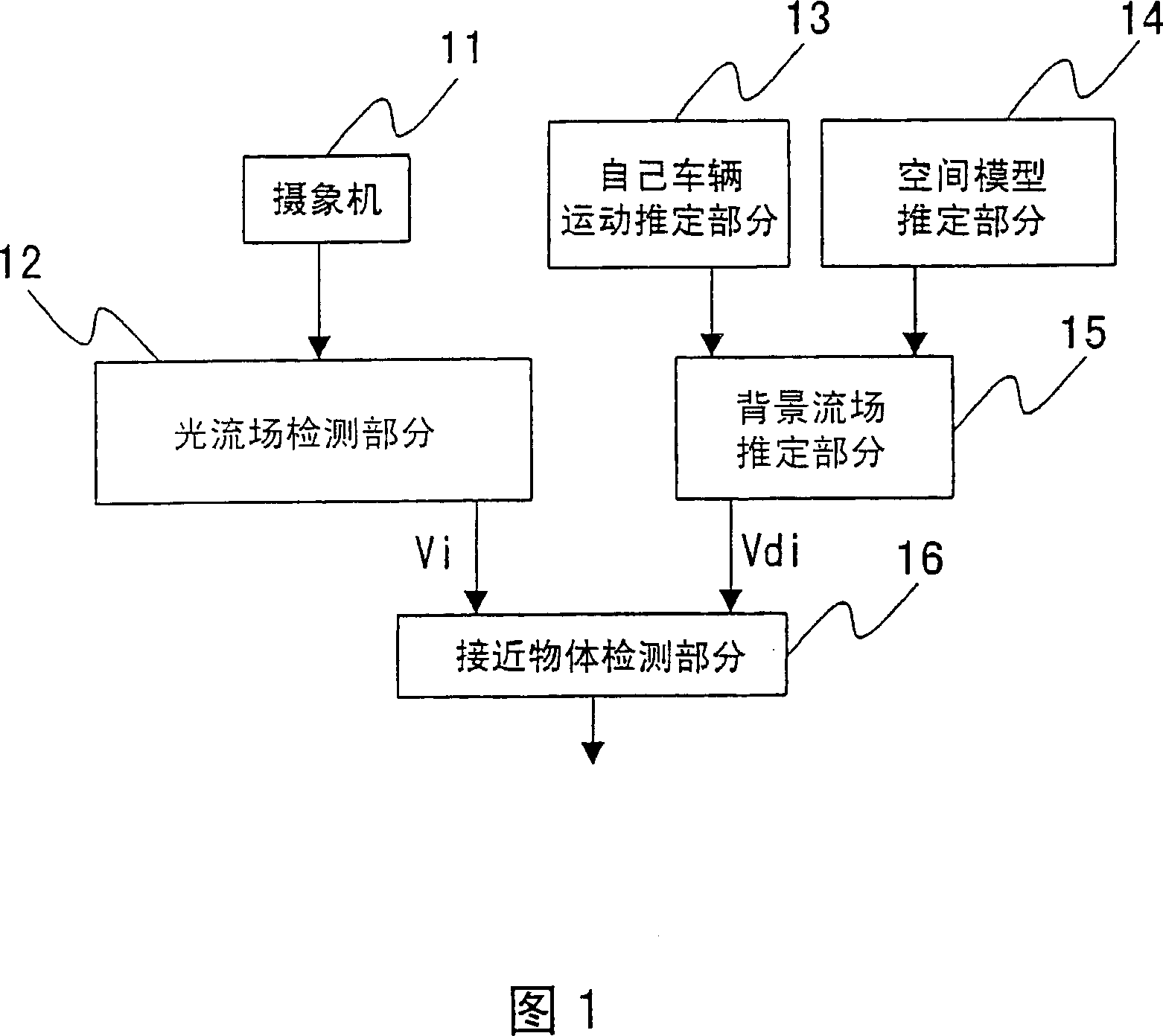
[0116]In the first embodiment of the present invention, the surroundings of the vehicle are monitored as follows. First, the optical flow field is obtained by taking images around the vehicle with a camera. Next, the corresponding relationship between the points on the camera image and the 3D coordinates in the real world is estimated as a "space model". As shown in FIG. 37, by applying perspective projection transformation to this space model, it is possible to correctly realize the correspondence between the points on the camera image and the 3D coordinates in the real world. And using this space model and the estimated own vehicle motion information, the optical flow field when each point on the image is assumed to be not a moving object but a background can be obtained through calculation. The optical flow field obtained in this way is cal...


PUM


Abstract

In a monitoring device for vehicles, an optical flow detection section determines an optical flow from an image taken with a camera. A background flow estimation section determines a background flow, which is a flow for the camera image under the assumption that the image is a background, based on the motion of the vehicle. An approaching object detection section detects motion of an object in the surroundings of the vehicle by comparing the optical flow with the background flow.

Description

[0001] This application is a divisional application of the application number "03123605.7", the title of the invention is "monitoring device, monitoring method and monitoring program", and the filing date is May 9, 2003. technical field [0002] The present invention relates to a monitoring technology for a vehicle which uses a camera to monitor the situation around the vehicle and detects approaching objects. Background technique [0003] Conventionally, various methods have been used for a monitoring device for a vehicle that monitors the situation around the vehicle and detects an approaching object. [0004] One of them is an obstacle sensor using radar or the like. However, although this method can reliably detect an obstacle, it is not suitable for complex judgments such as whether the obstacle is approaching or moving away. Moreover, since the influence of rainfall etc. is also great and the detection range is relatively narrow, it is difficult to detect an approachi...

Claims


Application Information

Patent Timeline
Patent Type & Authority Applications(China)
IPC IPC(8): G06T7/20H04N7/18
CPCG06K9/00805G06T7/2006G06T7/2066G06K9/00791G06T2207/30261G06T2207/10016G06T2207/10028G08G1/16G08G1/165G08G1/166G08G1/167G06T7/215G06T7/269G06V20/58B60R21/00
Inventor 佐藤智中川雅通登一生
Owner PANASONIC CORP
Features
  • R&D
  • Intellectual Property
  • Life Sciences
  • Materials
  • Tech Scout
  • Unparalleled Data Quality
  • Higher Quality Content
  • 60% Fewer Hallucinations
Learn More