
Dust collection device of vacuum cleaner

A technology of vacuum cleaners and dust collection devices, which is applied in the direction of suction filters, etc., which can solve the problems of reduced dust collection performance, large flow path resistance, and the inability of users to confirm collection with the naked eye, and achieve the effect of improving dust collection performance

Inactive Publication Date: 2007-05-30
LG ELECTRONICS (TIANJIN) APPLIANCES CO LTD
View PDF0 Cites 0 Cited by
  • Summary
  • Abstract
  • Description
  • Claims
  • Application Information

AI Technical Summary

Problems solved by technology

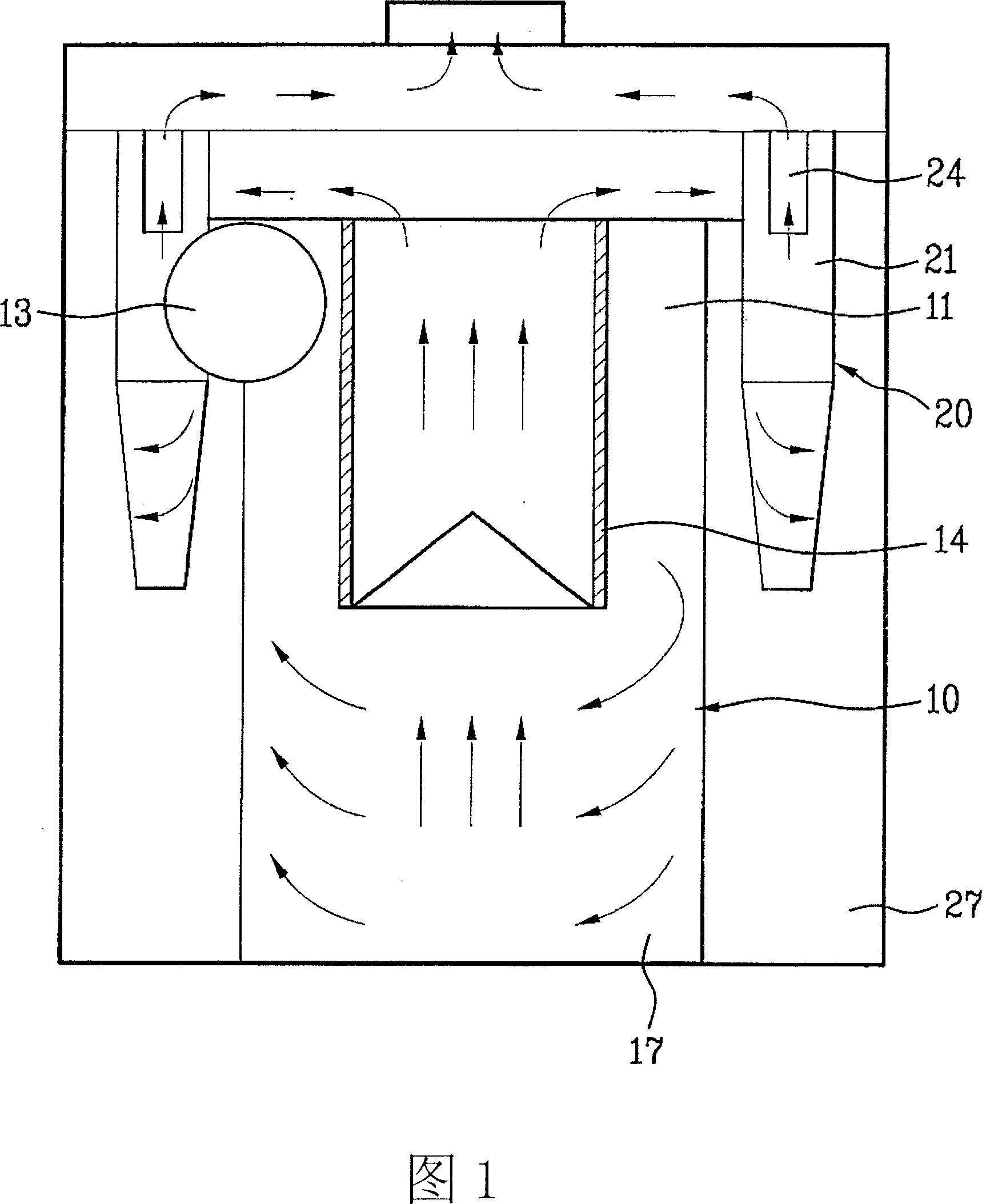
Therefore, the flow path resistance caused by the air flow is large, resulting in a problem that the dust collection performance is lowered
[0013] In addition, a plurality of secondary cyclone parts surround the outer peripheral surface of the primary cyclone part, so the user cannot visually confirm the dust bucket of the primary cyclone part for collecting relatively large dust.

Method used


Image

  • Dust collection device of vacuum cleaner
  • Dust collection device of vacuum cleaner
  • Dust collection device of vacuum cleaner

Examples


Embodiment 1

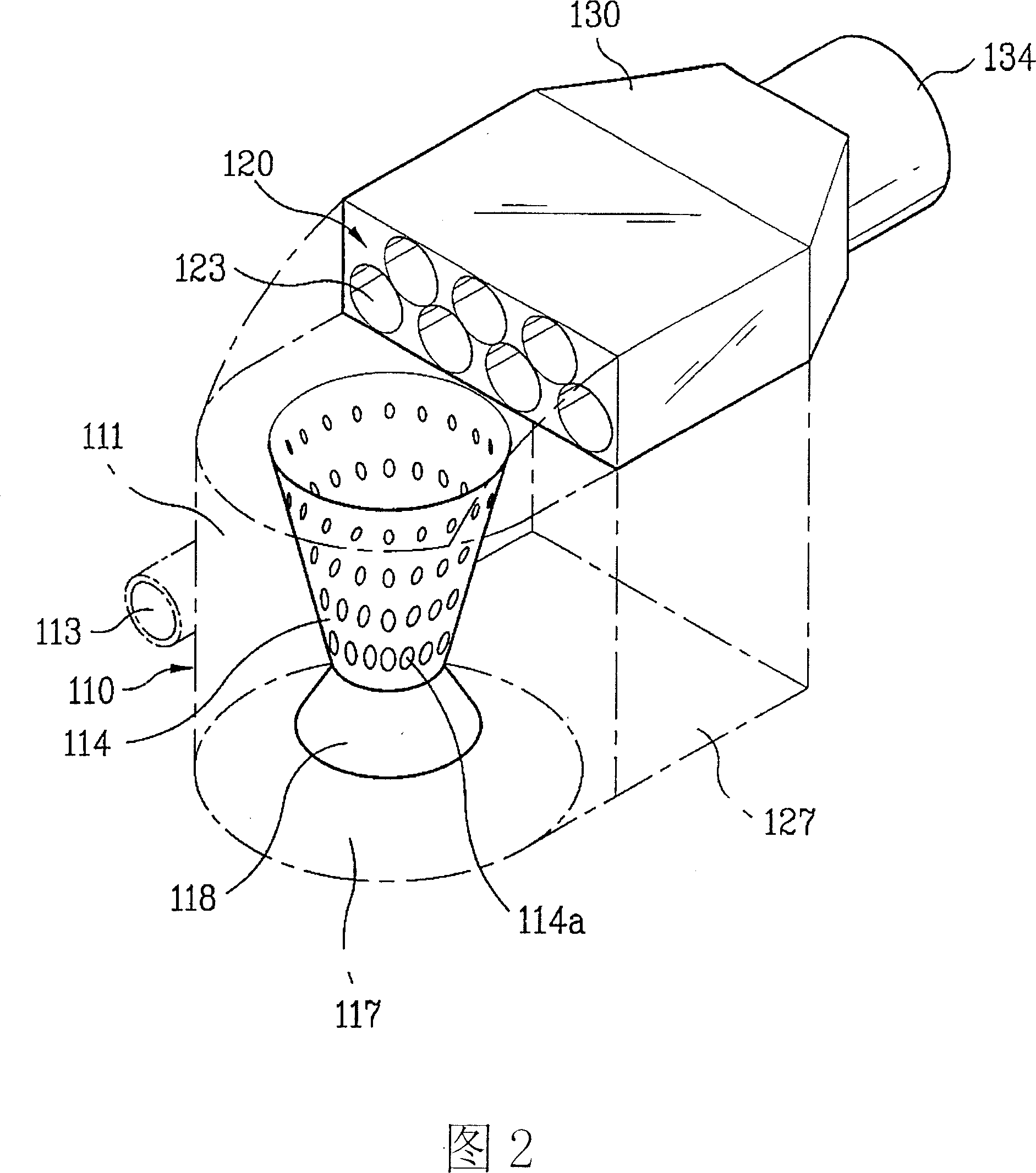
[0039] Referring to Fig. 2 to Fig. 4, the dust collecting device of the vacuum cleaner according to Embodiment 1 of the present invention will be described as follows.

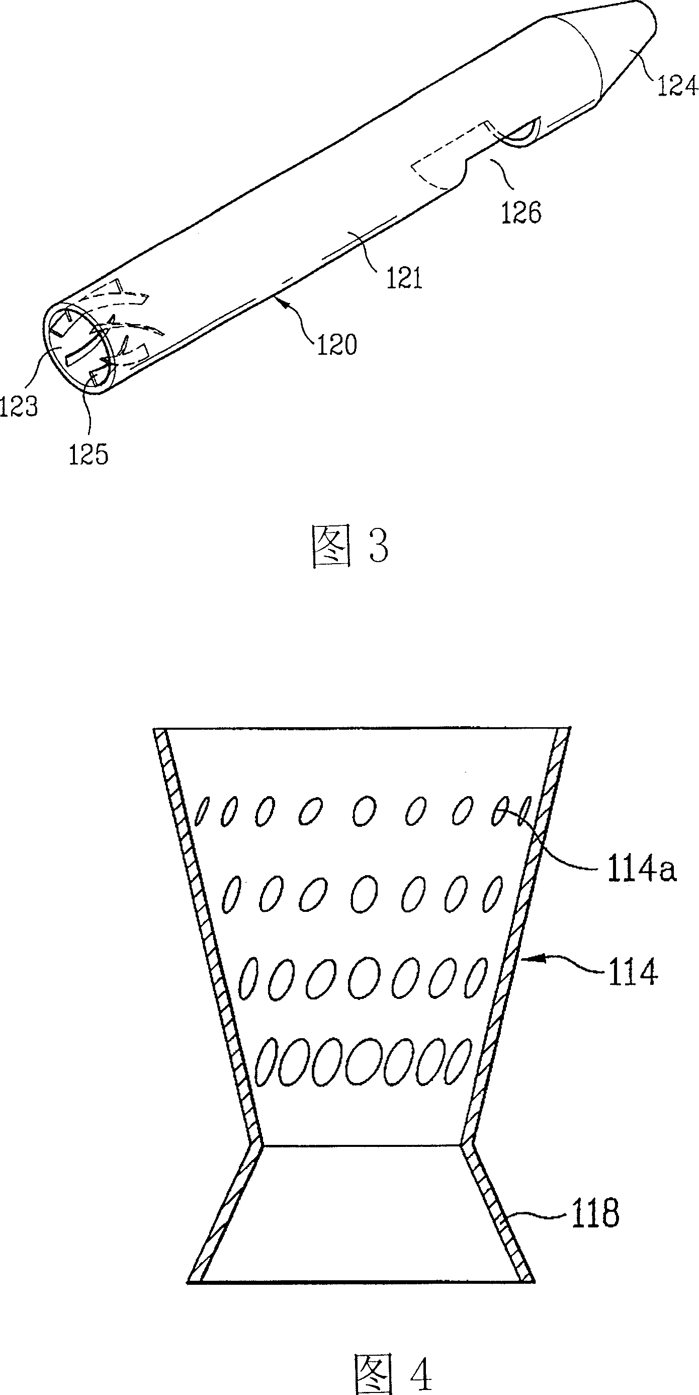
[0040] Fig. 2 is a perspective view of the internal structure of the dust collector according to Embodiment 1 of the present invention. Fig. 3 is a perspective view of a secondary cyclone section of the dust collector according to Embodiment 1 of the present invention. Fig. 4 is a plan view of a first outflow portion of the dust collector according to Embodiment 1 of the present invention.

[0041] The basic structure of this embodiment is like the structure in the prior art, including: the primary cyclone part 110 that separates the foreign matter contained in the air flowing into the interior by using the principle of the cyclone; the air discharged from the primary cyclone part 110 flows in, and A plurality of secondary cyclone parts 120 that separate foreign matter again from the inflowing air.

[0042] ...


PUM


Abstract

The invention discloses a dust collecting device of vacuum duster, which comprises the following parts: first cyclone part to flow foreign body in the air, multiple second cyclones to separate foreign body from the first cyclone, wherein the direction and air in the inlet is the same as the outlet of second cyclone.

Description

technical field [0001] The invention relates to a dust collecting device of a vacuum cleaner. In particular, it relates to a dust collecting device which utilizes the principle of a cyclone to collect foreign matter. Background technique [0002] Cyclone dust collection device is a device that uses the principle of cyclone to collect foreign matter such as dust contained in the air. The cyclone dust collection device is suitable for many fields, and as a household use, it is mainly suitable for vacuum cleaners. [0003] Recently, in order to improve the dust collection performance, a multi-cyclone dust collector equipped with a plurality of cyclone parts has begun to be used. [0004] Hereinafter, a dust collecting device of a vacuum cleaner in the prior art will be described with reference to FIG. 1 . [0005] The dust collecting device in the prior art includes: a primary cyclone dust collecting part 10 that collects relatively large dust in the air after inhaling pollu...

Claims


Application Information

Patent Timeline
IPC IPC(8): A47L9/16
Inventor 郑景善玄起卓金一中孙永福
Owner LG ELECTRONICS (TIANJIN) APPLIANCES CO LTD
Learn More