Suction means of dust collector

A vacuum cleaner and equipment technology, applied in the direction of suction nozzles, etc., can solve problems such as easy entanglement and difficult dust collection, and achieve the effect of improving dust collection performance

Inactive Publication Date: 2006-01-11
LG ELECTRONICS (TIANJIN) APPLIANCES CO LTD
View PDF0 Cites 10 Cited by
  • Summary
  • Abstract
  • Description
  • Claims
  • Application Information

AI Technical Summary

Problems solved by technology

[0009] In addition, because the brush 24 rotates 360° in one direction, foreign objects such as hair are easily entangled on the bristles 24b, and it is difficult to perform thorough vacuuming.

Method used


Image

  • Suction means of dust collector
  • Suction means of dust collector
  • Suction means of dust collector

Examples


Embodiment Construction

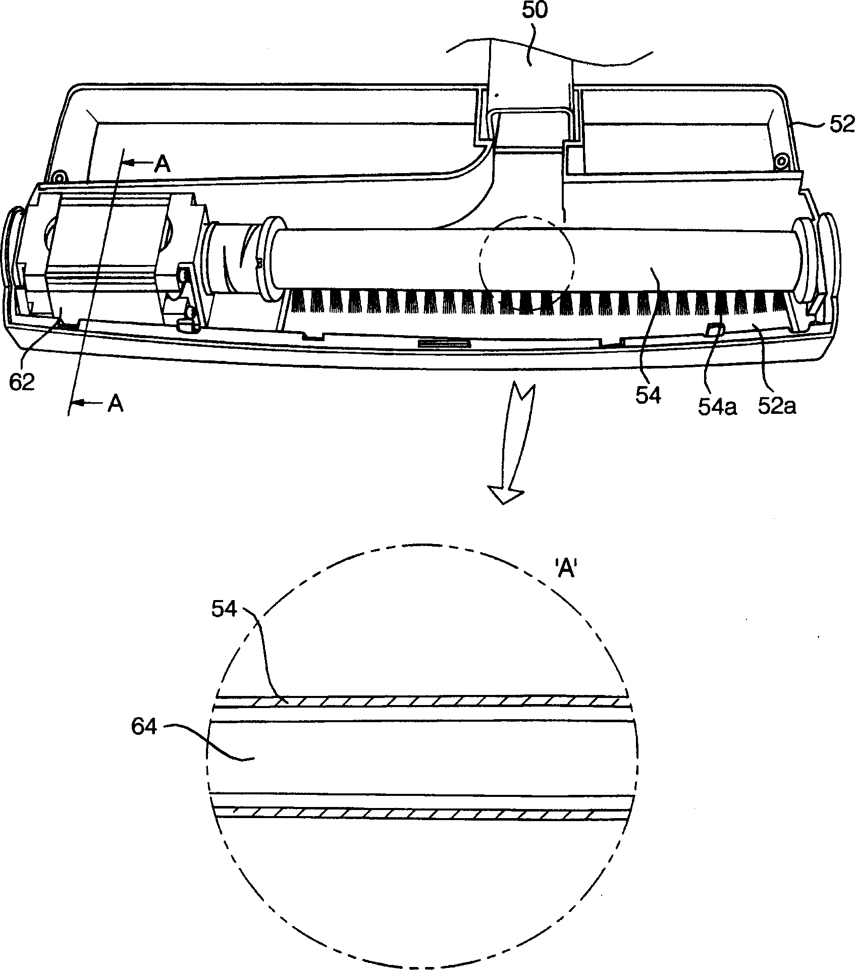
[0033] Embodiments of the present invention will be described in further detail below in conjunction with the accompanying drawings.

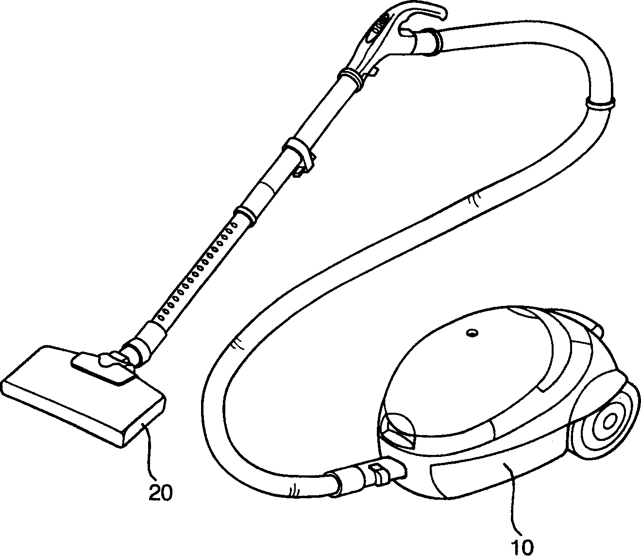
[0034] Such as Figure 3 to Figure 5 As shown, the vacuum cleaner suction device of the present invention includes a suction head 52 , a brush 54 , and driving parts 62 , 64 . The suction head 52 is connected to the machine body through the suction pipe 50, and is formed with a suction port 52a for sucking air and garbage in front of the ground. The brush 54 is rotatably arranged at the suction port 52a of the suction head 52, and brushes up the rubbish by rubbing against the ground to make it float. The driving parts 62 and 64 are directly connected with the brush 54 along the length direction of the brush 54 , and are arranged in the suction head 52 to drive the brush 54 to rotate.

[0035] On the suction head 52, corresponding to the entire length of the hairbrush 54, the suction port 52a of the suction head is formed along the up and down...


PUM


Abstract

A sucking unit of cleaner is composed of sucking head connected to main body with sucking fan, rotary brush at the sucking inlet of said sucking head, and driver connected directly to the said rotary brush. Its advantages are no dead area, and low power loss, vibration and noise.

Description

technical field [0001] The invention relates to a vacuum cleaner, in particular to a vacuum cleaner suction device which is directly connected with a brush and a motor and rotates back and forth within a certain angle range to improve the dust collection performance. Background technique [0002] figure 1 It is a schematic diagram of a common vacuum cleaner. [0003] Such as figure 1 As shown, a common vacuum cleaner includes a body 10 and a suction device 20 . Body 10 inside is equipped with the blower that produces suction and the dust bag that dresses rubbish such as dust. The inhalation device 20 is connected to the body 10 to inhale air and garbage. When vacuuming, the inside of the body 10 generates suction to suck the air and rubbish in, the rubbish is packed in the dust bag, and the air is discharged outside again after being purified. [0004] figure 2 It is a three-dimensional schematic diagram of vacuum cleaner suction equipment in the prior art. [0005] ...

Claims


Application Information

Patent Timeline
IPC IPC(8): A47L9/04
Inventor 李耀汉金相永
Owner LG ELECTRONICS (TIANJIN) APPLIANCES CO LTD
Why Eureka
Try Eureka