
Vacuum cleaner

a vacuum cleaner and vacuum technology, applied in vacuum cleaners, cleaning equipment, domestic applications, etc., to achieve the effect of minimizing the torque loss of the main brush and improving the performance of dust suction

Active Publication Date: 2017-05-25
SAMSUNG ELECTRONICS CO LTD
View PDF6 Cites 15 Cited by
  • Summary
  • Abstract
  • Description
  • Claims
  • Application Information

AI Technical Summary

Benefits of technology

The patent text describes a vacuum cleaner that reduces the loss of power in its main brush, improves the vacuum's ability to collect dust around walls, and maximizes the torque of the brush by lifting it up based on the type of surface being cleaned.

Problems solved by technology

Also, an exemplary embodiment is not required to overcome the disadvantages described above, and an exemplary embodiment may not overcome any of the problems described above.

Method used


Image

  • Vacuum cleaner
  • Vacuum cleaner
  • Vacuum cleaner

Examples


Embodiment Construction

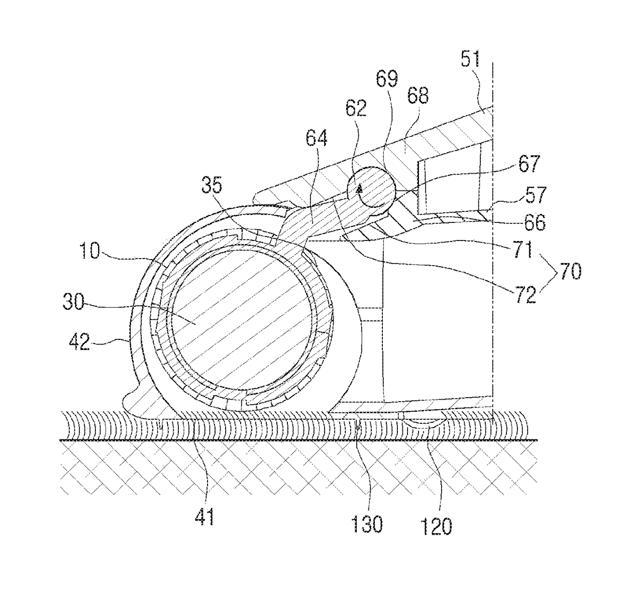
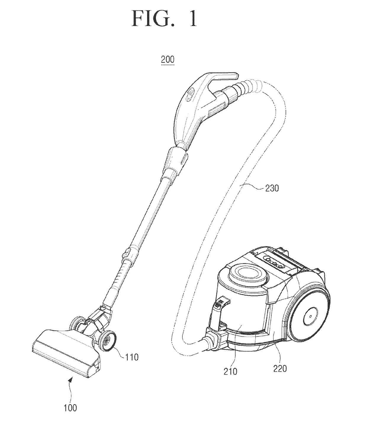
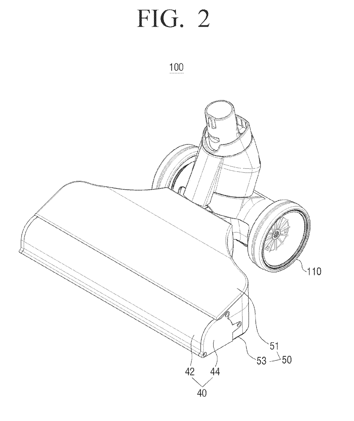
[0046]Hereinafter, the exemplary embodiments are described in greater detail with reference to the accompanying FIGS. 1 to 13. The matters defined in the description, such as detailed construction and elements, are provided to assist in a comprehensive understanding of the exemplary embodiments. Thus, it is understood that the exemplary embodiments can be carried out without those specifically defined matters.

[0047]Various embodiments will now be described more fully with reference to the accompanying drawings in which some embodiments are shown. The techniques described herein are exemplary, and should not be construed as implying any particular limitation on the present disclosure. It should be understood that various alternatives, combinations and modifications could be devised by those skilled in the art. In the following description, unless otherwise described, the same reference numerals are used for the same elements when they are depicted in different drawings.

[0048]FIG. 1 i...


PUM


Abstract

A nozzle assembly for a vacuum cleaner includes a driving member including a first driving shaft and a second driving shaft in both sides thereof, a first drum of which one end is coupled to the first driving shaft to be driven by directly receiving driving force of the first driving shaft, and a second drum of which one end is coupled to the second driving shaft to be driven by directly receiving driving force of the second driving shaft.

Description

CROSS-REFERENCE TO RELATED APPLICATIONS[0001]This application claims priority from Korean Patent Application No. 10-2015-0162319, filed on Nov. 19, 2015, in the Korean Intellectual Property Office, the disclosure of which is incorporated herein by reference in its entirety.BACKGROUND OF THE INVENTION[0002]Field of the Invention[0003]Apparatuses and methods consistent with exemplary embodiments relate to a vacuum cleaner, and more particularly, to a vacuum cleaner capable of changing a position of a drum in which a brush is installed according to a type of surface to be cleaned and maximizing an area of the surface to be cleaned.[0004]Description of the Related Art[0005]In general, a vacuum cleaner may include a cleaner main body in which a vacuum suction device and a dust collector are installed and a nozzle assembly coupled to the main body. The nozzle assembly may suck the air including dirt through negative pressure formed in the vacuum suction device and divide the dirt from the...

Claims


Application Information

Patent Timeline
Patent Type & Authority Applications(United States)
IPC IPC(8): A47L9/04A47L5/34A47L5/36A47L5/30
CPCA47L9/0494A47L5/30A47L9/0411A47L9/0477A47L5/362A47L5/34A47L9/0455
Inventor KIM, SHINPAIK, SOK-WONLIM, WON-KYULEE, JAE-MINLEE, HYUN-JUJUNG, YOUNG-SUNGHA, JUNG-SU
Owner SAMSUNG ELECTRONICS CO LTD
Learn More