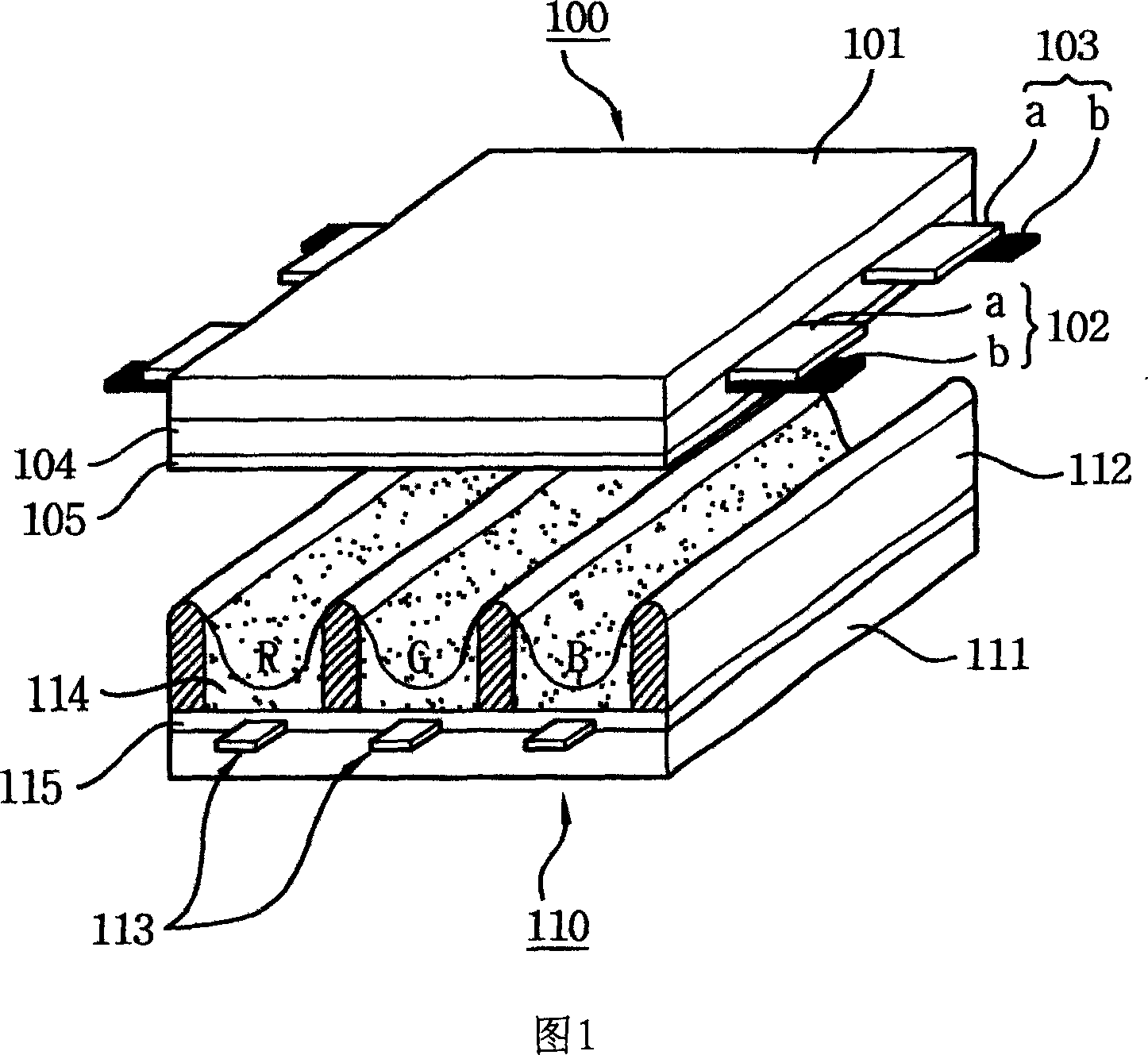
Plasma display device and its driving method
A plasma and display device technology, applied in identification devices, static indicators, instruments, etc., can solve problems such as increased costs, achieve the effects of improving image quality, improving brightness characteristics, and improving driving methods
- Summary
- Abstract
- Description
- Claims
- Application Information
AI Technical Summary
Problems solved by technology
Method used
Image

Examples
Embodiment 1
[0077] FIG. 4 is a schematic diagram of a plasma display device in Embodiment 1 of the present invention.
[0078] Referring to FIG. 4, the plasma display device in Embodiment 1 of the present invention includes: a plasma display device including scan electrodes Y1 to Yn and sustain electrodes Z, and a plurality of positioning electrodes X1 to Xm intersecting the scan electrodes and sustain electrodes Z. The display panel 100; the digital drive unit 122 that provides data to the positioning electrodes X1 to Xm formed in the lower substrate (not shown) of the plasma display panel 100; the scan drive unit 123 that drives the scan electrodes Y1 to Yn; drives the common electrodes, That is, the sustain driving part 124 of the sustain electrode Z; when driving the plasma display panel, controls the digital driving part 122, the timing control part 121 of the scanning driving part 123 and the sustain driving part 124; provides driving to each driving part 122, 123, 124 voltage to dr...
Embodiment 2
[0125] FIG. 9 is a schematic diagram of a plasma display device in Embodiment 2 of the present invention.
[0126] Referring to FIG. 9 , the plasma display device in Embodiment 2 of the present invention includes: a plasma display including scan electrodes Y1 to Yn and sustain electrodes Z and a plurality of positioning electrodes X1 to Xm intersecting the scan electrodes and sustain electrodes Z The panel 100; the digital drive unit 922 that provides data to the positioning electrodes X1 to Xm formed in the lower substrate (not shown) of the plasma display panel 900; the scan drive unit 923 that drives the scan electrodes Y1 to Yn; drives the common electrodes, that is, Sustain driving part 924 of sustain electrode Z; when driving the plasma display panel, control digital driving part 922, scan driving part 923 and timing control part 921 of sustain driving part 924; supply driving voltage to each driving part 922, 923, 924 The driving voltage generation part 925.
[0127]Th...
Embodiment 3
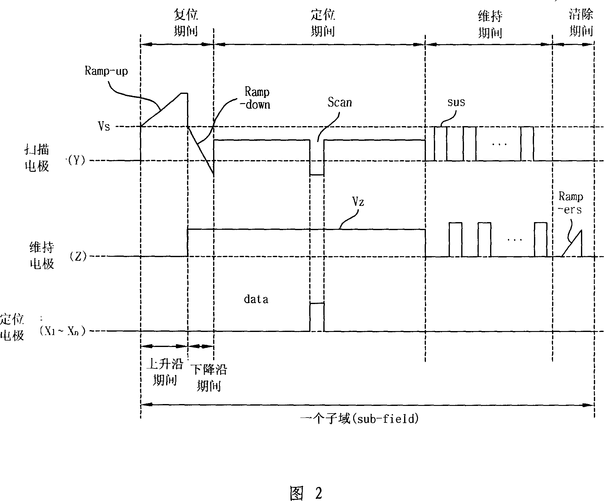
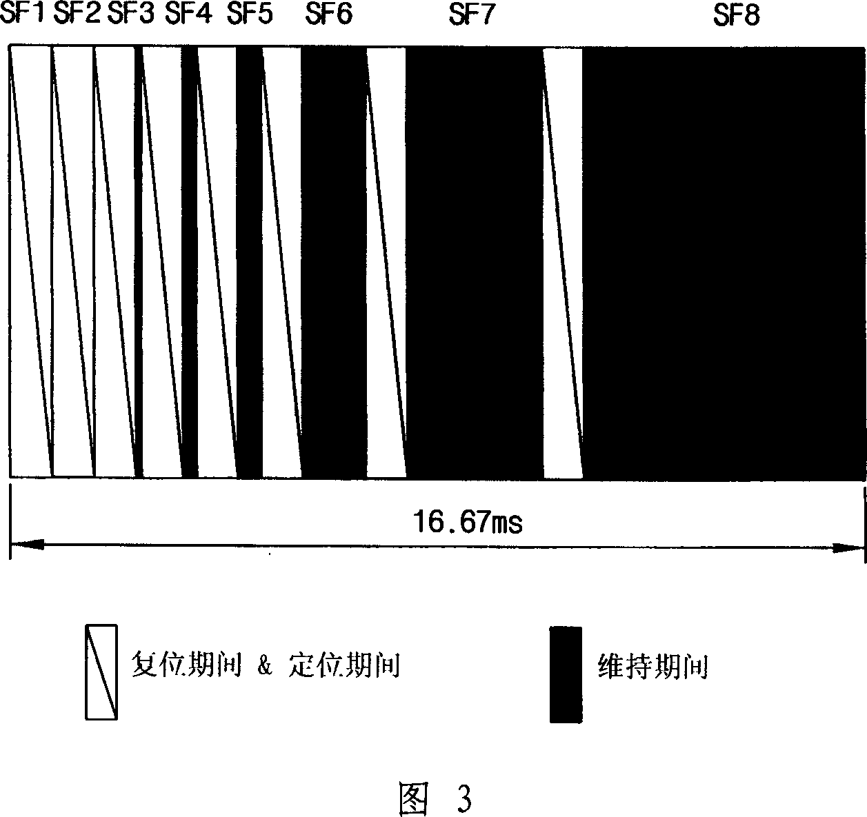
[0135] The structure of the plasma display device in Embodiment 3 of the present invention is the same as that of the plasma display devices in Embodiment 1 and Embodiment 2 of the present invention, so it will be omitted here. Only, the timing control unit (not shown) in Embodiment 3 of the present invention adjusts the number of sub-fields and the number of sub-fields (sub-fields) according to the load (load) amount of the image signal displayed on the plasma display panel. The weight value (weight) of the number of sustain pulses allocated in the field) is adjusted according to the weight value (weight) of the number of sub-fields (sub-field) and the number of sustain pulses allocated in the sub-field (sub-field), in order to make A scan drive unit (not shown) controls the scan drive unit by partially scanning the plurality of scan electrodes during positioning of at least one sub-field among the plurality of sub-fields.
[0136] FIG. 11 is a schematic diagram of the workin...
PUM
 Abstract
Description
Claims
Application Information
 - R&D Engineer
- R&D Manager
- IP Professional
- Industry Leading Data Capabilities
- Powerful AI technology
- Patent DNA Extraction
Browse by: Latest US Patents, China's latest patents, Technical Efficacy Thesaurus, Application Domain, Technology Topic.
© 2024 PatSnap. All rights reserved.Legal|Privacy policy|Modern Slavery Act Transparency Statement|Sitemap