Positioning structure for tool head pivot-swing

A technology of positioning structure and head, applied in the direction of manufacturing tools, hand-held tools, wrenches, etc., to achieve the effect of increasing the force range

Inactive Publication Date: 2007-06-13
谢智庆
View PDF0 Cites 1 Cited by
  • Summary
  • Abstract
  • Description
  • Claims
  • Application Information

AI Technical Summary

Problems solved by technology

[0007] The main technical problem to be solved by the present invention is to overcome the above-mentioned defects in the prior art, and provide a tool head pivoting positioning structure, which uses the strength of the two tooth-shaped sections to engage with each other, and when the user's strength If it is too large, there will be no problem of protruding, and it can increase the range of force applied by the user when screwing and locking the workpiece, thereby avoiding the disadvantage that the user needs to reciprocate the wrench body many times to lock the workpiece

Method used


Image

  • Positioning structure for tool head pivot-swing
  • Positioning structure for tool head pivot-swing
  • Positioning structure for tool head pivot-swing

Examples


Embodiment Construction

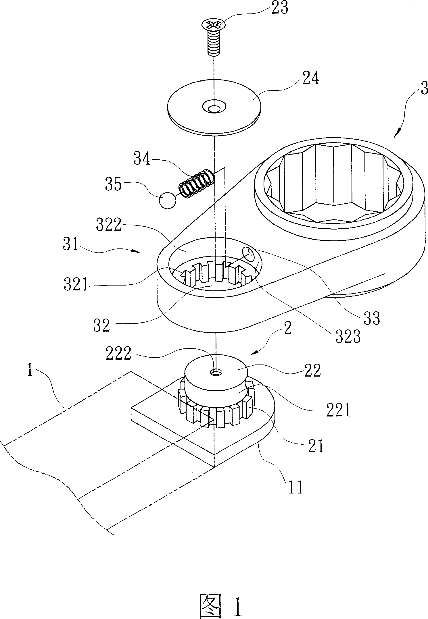
[0043] Please refer to FIG. 1 to FIG. 5 , which show the structure of the selected embodiment of the present invention.

[0044] The present invention is a tool head pivot positioning structure, comprising: a wrench body 1 , a first engaging unit 2 and a head body 3 .

[0045] One end of the wrench body 1 has a fixing unit 11 , and in this embodiment, the fixing unit 11 is lower than the height of the wrench body 1 .

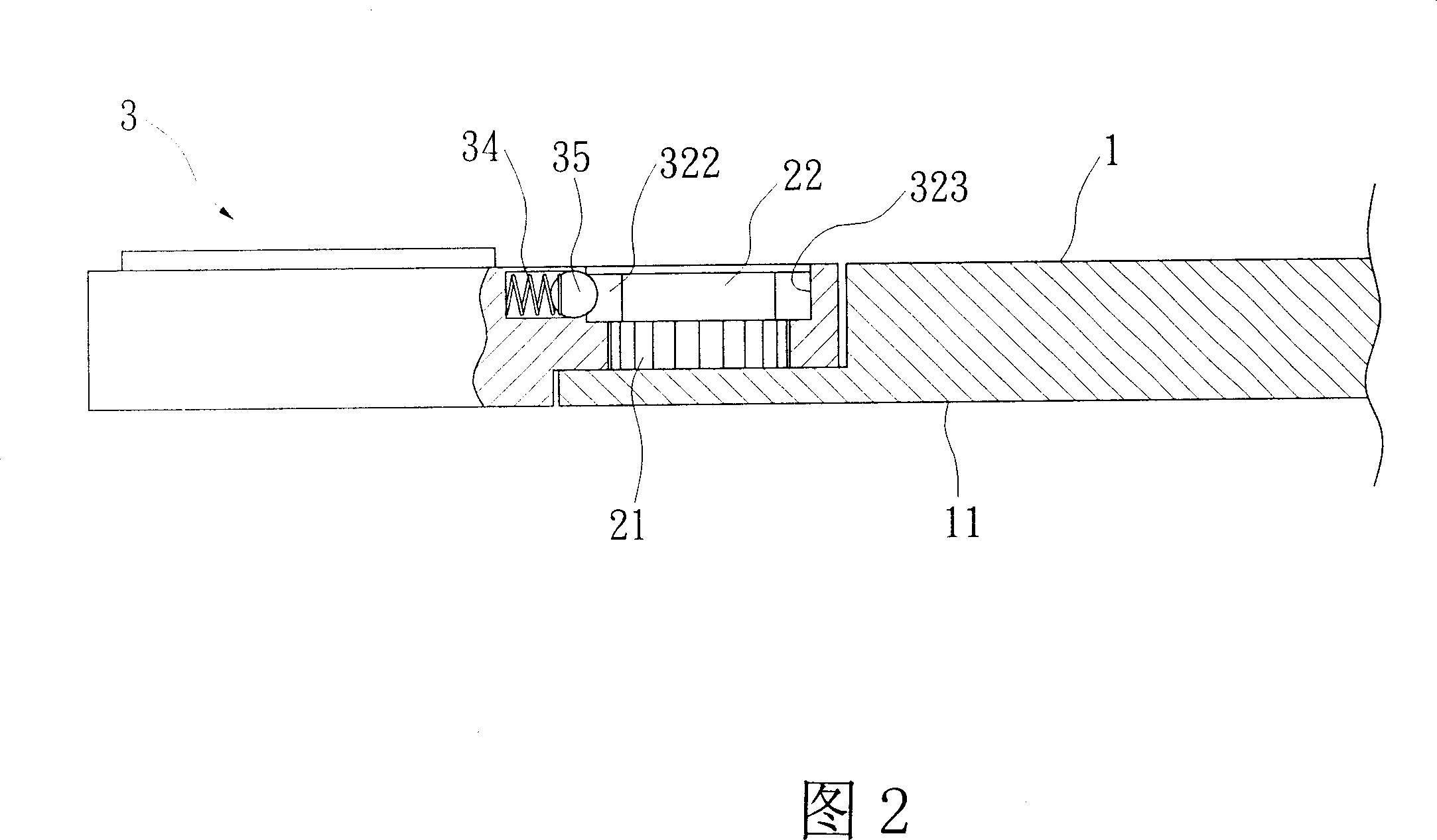
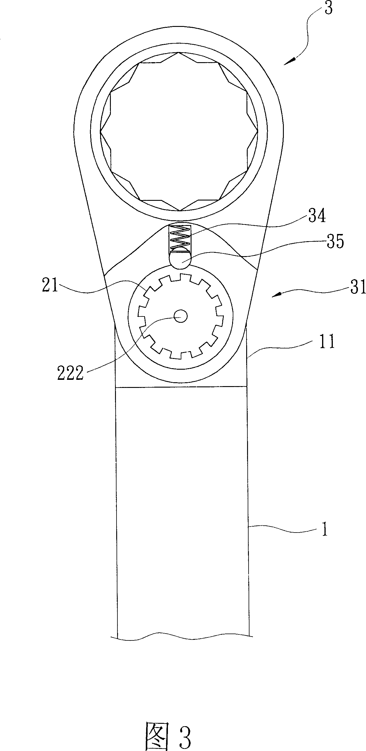
[0046] The first engaging unit 2 is the fixing unit 11 fixed on the wrench body 1, and the first engaging unit 2 is composed of a first engaging unit 21 and a cylinder 22. In this embodiment, the first The first engaging unit 21 of the engaging portion 2 is a cylinder with an external toothed segment.

[0047] One side of the head body 3 has a second engaging unit 31 which is engaged with the above-mentioned first engaging unit 2 , and the two can be combined and disengaged from each other. The second engaging unit 31 has an opening 32 , which passes through t...


PUM


Abstract

The present invention relates to a head portion pivoted swinging location structure of tool. Said structure includes a wrench self-body, its one end is equipped with a fixing unit; a first combination unit, it is fixed in fixing unit of wrench self-body, and said first combination unit is formed from a first fastening unit and a column body; a head portion self-body, its one side is equipped with a second combination unit, said second combination unit can be combined with said first combination unit, both they can be mutually combined and separated, said second combination unit has an opening, said opening is passed through said head portion self-body, said opening interior is equipped with a second fastening unit, over said second fastening unit an annular space is set, said annular space has an inner wall, one side of inner wall of annular space which is opposite to wrench self-body possesses a hole, said hole is extended into the head portion interior and is used for containing an etastic element and a barrier element. Said invention can increase force-applying range of user when a workpiece is rotatively locked by said user.

Description

technical field [0001] The invention relates to a tool head pivoting positioning structure. Background technique [0002] The existing wrench head positioning structure is shown in FIG. 6 , which includes: a wrench body 6 , a concave joint unit 7 and a head body 8 . [0003] The concave connection unit 7 is arranged at one end of the wrench body 6 , and has a through hole 72 on the bottom surface 71 of the depression to communicate with the wrench body 6 at an appropriate distance, and for a spring 73 and a steel ball 74 to be inserted therein. [0004] The head body 6 has a male joint unit 61 for relative engagement with the female joint unit 7, and then the male joint unit 61 and the female joint unit 7 are pivotally connected to each other by a pin 62, and outside the male joint unit 61 There are several tooth-shaped sections 611 on the edge, for the above-mentioned spring 73 to push against the steel ball 74 to insert and engage, thereby fixing the head body 8 . [000...

Claims


Application Information

Patent Timeline
Patent Type & Authority Applications(China)
IPC IPC(8): B25B23/00B25G3/38
Inventor 谢智庆
Owner 谢智庆
Why Eureka
Try Eureka