Organic electric luminous element

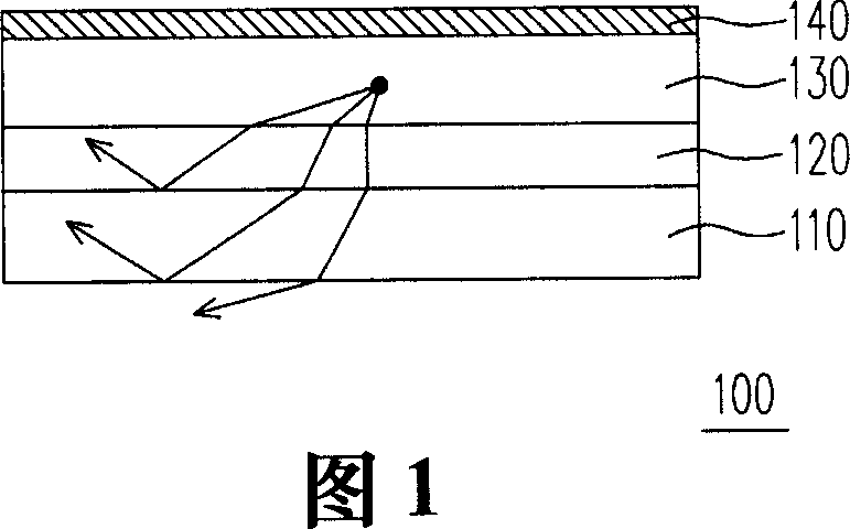
An electroluminescent element and luminescent technology, applied in the direction of electrical components, electric solid devices, circuits, etc., can solve the problems of low luminous efficiency, reflection or refraction, and inability to provide double-sided light emission of the light-emitting element 100

Inactive Publication Date: 2007-06-13
CHUNGHWA PICTURE TUBES LTD
View PDF0 Cites 11 Cited by
  • Summary
  • Abstract
  • Description
  • Claims
  • Application Information

AI Technical Summary

Problems solved by technology

[0005] However, the problem with the known organic electroluminescent element 100 is that the light emitted by the organic functional layer 130 is likely to be reflected or refracted due to the difference in the refractive index of each layer in the element.
Therefore, most of the light emitted by the organic functional layer 13

Method used


Image

  • Organic electric luminous element
  • Organic electric luminous element
  • Organic electric luminous element

Examples


no. 1 example

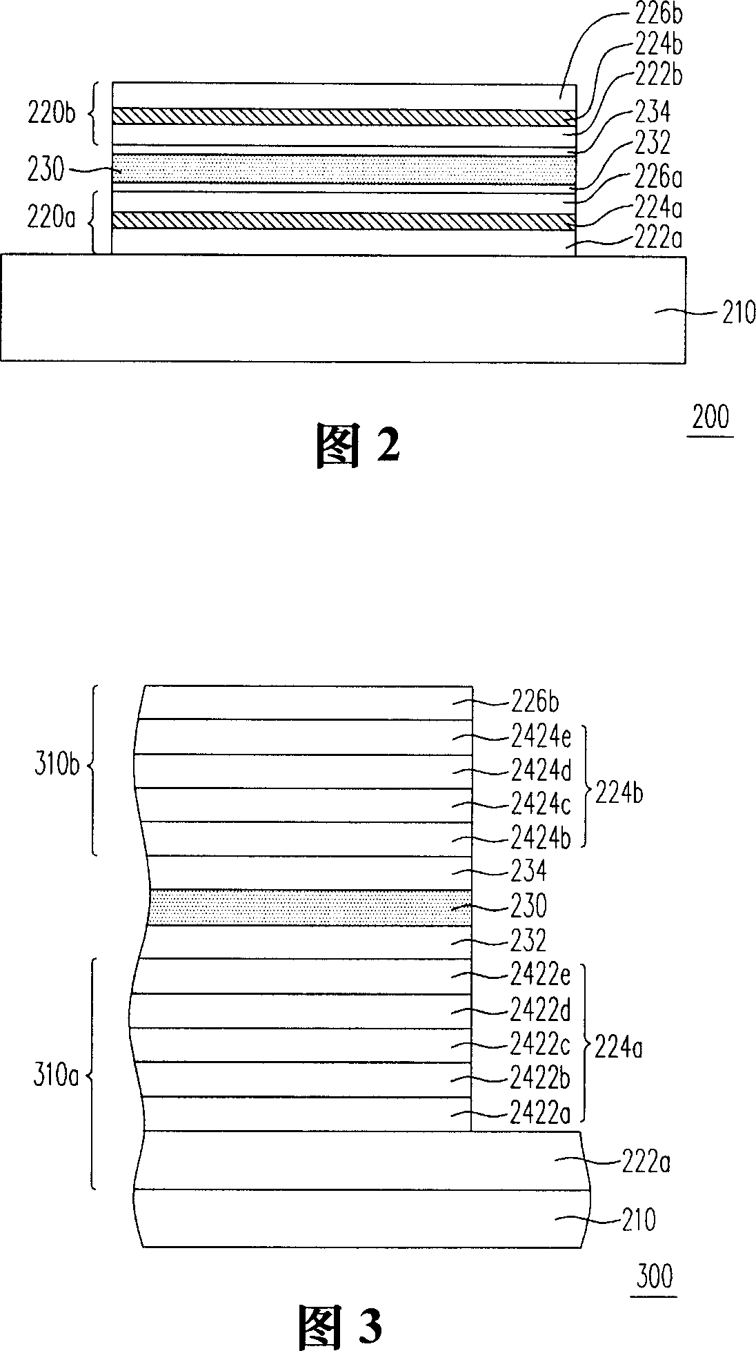
[0042] FIG. 2 is a schematic cross-sectional view of an organic electroluminescent device according to a first embodiment of the present invention. Referring to FIG. 2, the organic electroluminescent device 200 of this embodiment includes a transparent substrate 210, a plurality of organic electroluminescent units 220a, 220b and a reflective electrode layer 230, wherein these organic electroluminescent units 220a and 220b are stacked on the transparent substrate 210, and the reflective electrode layer 230 is disposed between the organic electroluminescence units 220a and 220b. In addition, the transparent substrate 210 is, for example, a glass substrate, a quartz substrate, a plastic substrate or a flexible substrate. In this embodiment, the organic electroluminescent element 200 further includes a first-type doped layer 232 and a second-type doped layer 234, and the reflective electrode layer 230 is disposed on the first-type doped layer 232 and the second-type doped layer. ...

no. 2 example

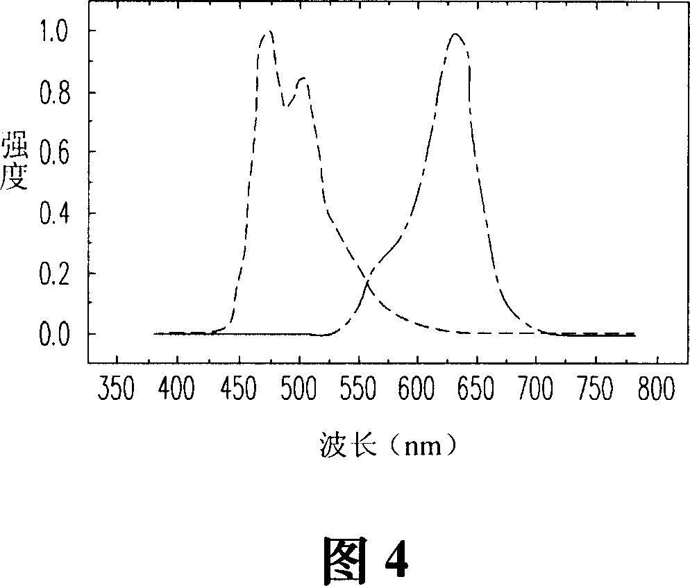
[0049] 3 is a schematic cross-sectional view of an organic electroluminescent device according to a second embodiment of the present invention. Please refer to FIG. 3 , the second embodiment is similar to the first embodiment, the difference is that: in the organic electroluminescence device 300 of this embodiment, the reflective electrode layer 230 is used as the common electrode layer. In other words, the reflective electrode layer 230 is disposed between two adjacent organic functional layers 224a and 224b. It is worth mentioning that since the reflective electrode layer 230 can be formed by vapor deposition, the organic functional layer 224 a will not be damaged during the process of forming the reflective electrode layer 230 .

[0050] More specifically, the reflective electrode layer 230 , the organic functional layer 224 a and the transparent anode layer 222 a constitute the organic electroluminescent unit 310 a, so the reflective electrode layer 230 is a cathode layer ...


PUM

PropertyMeasurementUnit
Thicknessaaaaaaaaaa
Thicknessaaaaaaaaaa

Abstract

The organic electroluminescent cell includes transparent base plate, organic electroluminescent cells, and reflecting electrode layers. These organic electroluminescent cells are piled on the base plate. The reflecting electrode layer is setup between adjacent two organic electroluminescent cells. Thus, the invention provides function of display on two sides.

Description

technical field [0001] The invention relates to a light-emitting element, and in particular to an organic electroluminescence element. Background technique [0002] Organic electro-luminescent device (OELD) is a device that utilizes the self-luminous properties of organic functional materials to achieve display effects. According to the molecular weight of organic functional materials, it is divided into small molecule organic There are two types of luminescent devices (Small Molecule OELD, SM-OELD) and polymer electroluminescent devices (Polymer Electro-Luminescent Device, PELD). Both light emitting structures are composed of a pair of electrodes and an organic functional layer, and the structures of known organic electroluminescent elements will be described in detail later. [0003] FIG. 1 is a schematic structural diagram of a known organic electroluminescent element. Please refer to FIG. 1 , a known organic electroluminescent element 100 includes a substrate 110, an a...

Claims


Application Information

Patent Timeline
IPC IPC(8): H01L51/52
Inventor 张展晴黄孝文陈金鑫汤舜钧闾俊中
Owner CHUNGHWA PICTURE TUBES LTD
Why Eureka
Try Eureka