

Taper ring transmission with surface optimization of contact region
A transmission and cone ring technology, applied in friction transmission, belt/chain/gear, mechanical equipment, etc., can solve problems such as reduced efficiency, increased transmission wear, and difficult design of cone ring transmissions
- Summary
- Abstract
- Description
- Claims
- Application Information
AI Technical Summary
Problems solved by technology
Method used
Image

Examples
Embodiment Construction
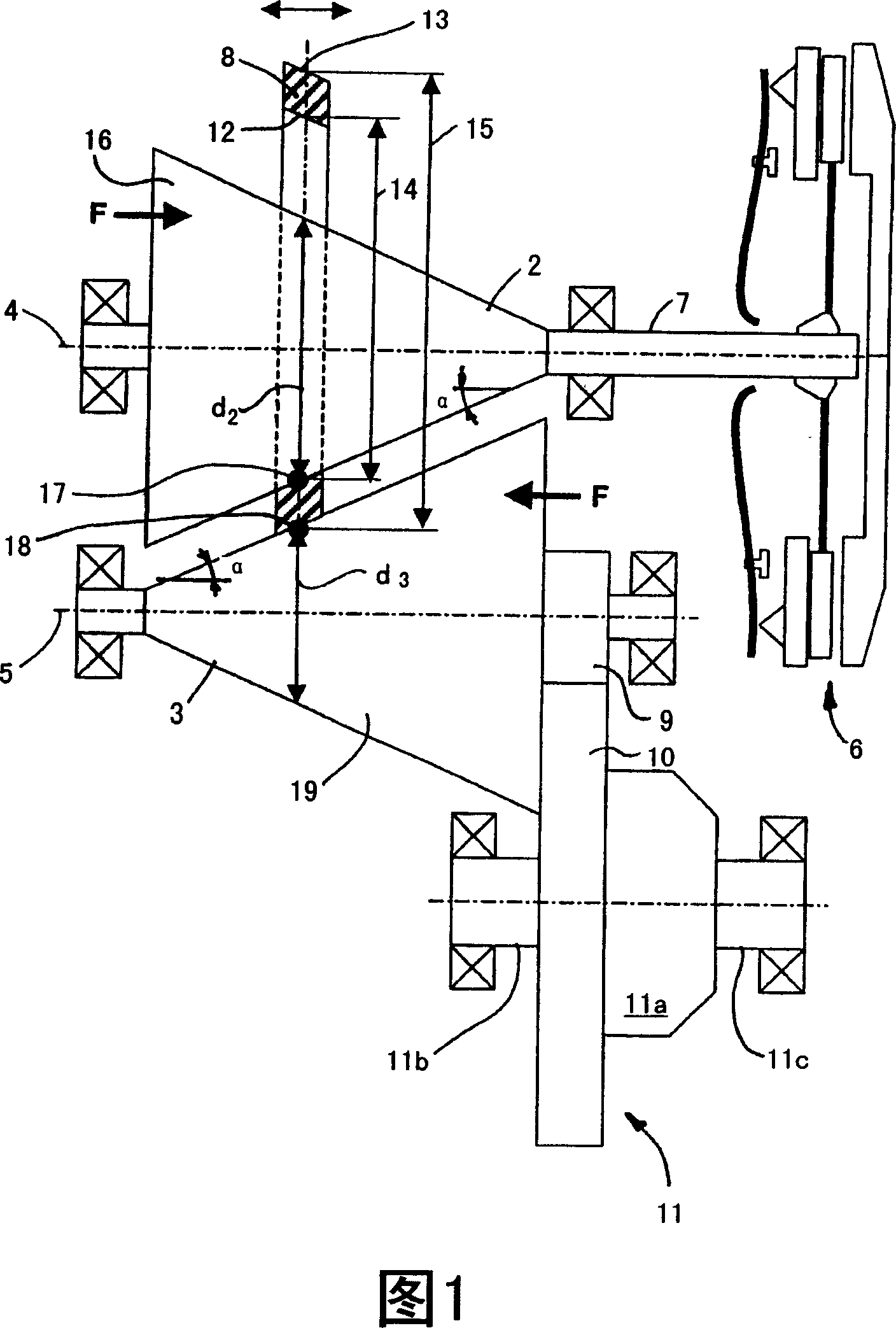
[0024] FIG. 1 shows a conical ring transmission designated as a whole by 1 . The bevel ring transmission 1 has a first conical friction wheel 2 and a second conical friction wheel 3 . The conical friction wheels 2 , 3 are arranged opposite to each other, wherein their axes of rotation run parallel and are spaced apart from each other. The axes of rotation of the conical friction wheels 2 , 3 are indicated by dashed lines 4 , 5 .
[0025] In addition to the cone ring transmission 1 , FIG. 1 also shows a clutch 6 of a motor vehicle, which is not further shown here. The clutch 6 is non-rotatably connected to the first conical friction wheel 2 via a shaft 7 . In the closed state, the clutch 6 transmits the torque via the shaft to the first conical friction wheel 2 . In order to transmit the torque from the first conical friction wheel 2 to the second conical friction wheel 3, a friction ring 8 is provided, which interacts with the two conical friction wheels 2, 3 and surrounds ...
PUM
 Abstract
Description
Claims
Application Information